




Guide de l'installateur Energy Monitor + EMS
Contenu de la boîte
Box contents for the split-core and flexible kits, the monitor's connections, the port map and the voltage harness colours.
If anything is missing or damaged, contact NeoCharge support before you start: +1 888 944 5581, support@getneocharge.com.
Box contents
Both kits include:
- NeoCharge Energy Monitor, with the back-label card (serial number and installer PIN)
- Two branch 50 A current transformers (CTs) with 22 AWG leads and screw-terminal plugs, for ports 3 and 4
- Voltage harness: 7.6 mm screw-terminal plug with four 16 AWG leads (black L1, red L2, white N, blue L3)
- Wi-Fi antenna assembly with knockout plug



Split-core CT kit
Also in the box:
- Two main 200 A split-core CTs with 22 AWG leads and screw-terminal plugs, for ports 1 and 2
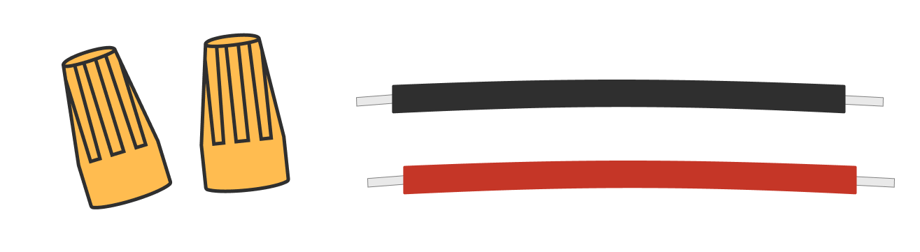
- Wire nuts and splicing wires

Flex (Rogowski) kit
Also in the box:
- Two flexible Rogowski coils, each with an integrator and a twisted signal cable, for ports 1 and 2
- One 12 V sensor power supply: black and red 12 V output split to two signal wires (each with a 4-pin plug for an integrator and a 2-pin plug for port 1 or 2), and a black + white AC input (black to L1, white to L2)
- Two 5-port Wago lever connectors, two wire nuts, and black and red splicing wires
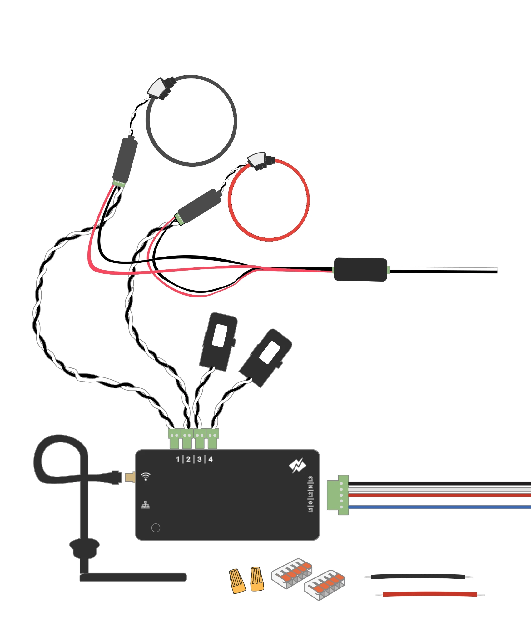
Use production kits only: the harness, power supply and integrators as shipped. Don't mix in parts from sample kits. More in Flexible (Rogowski) sensors.
Monitor connections
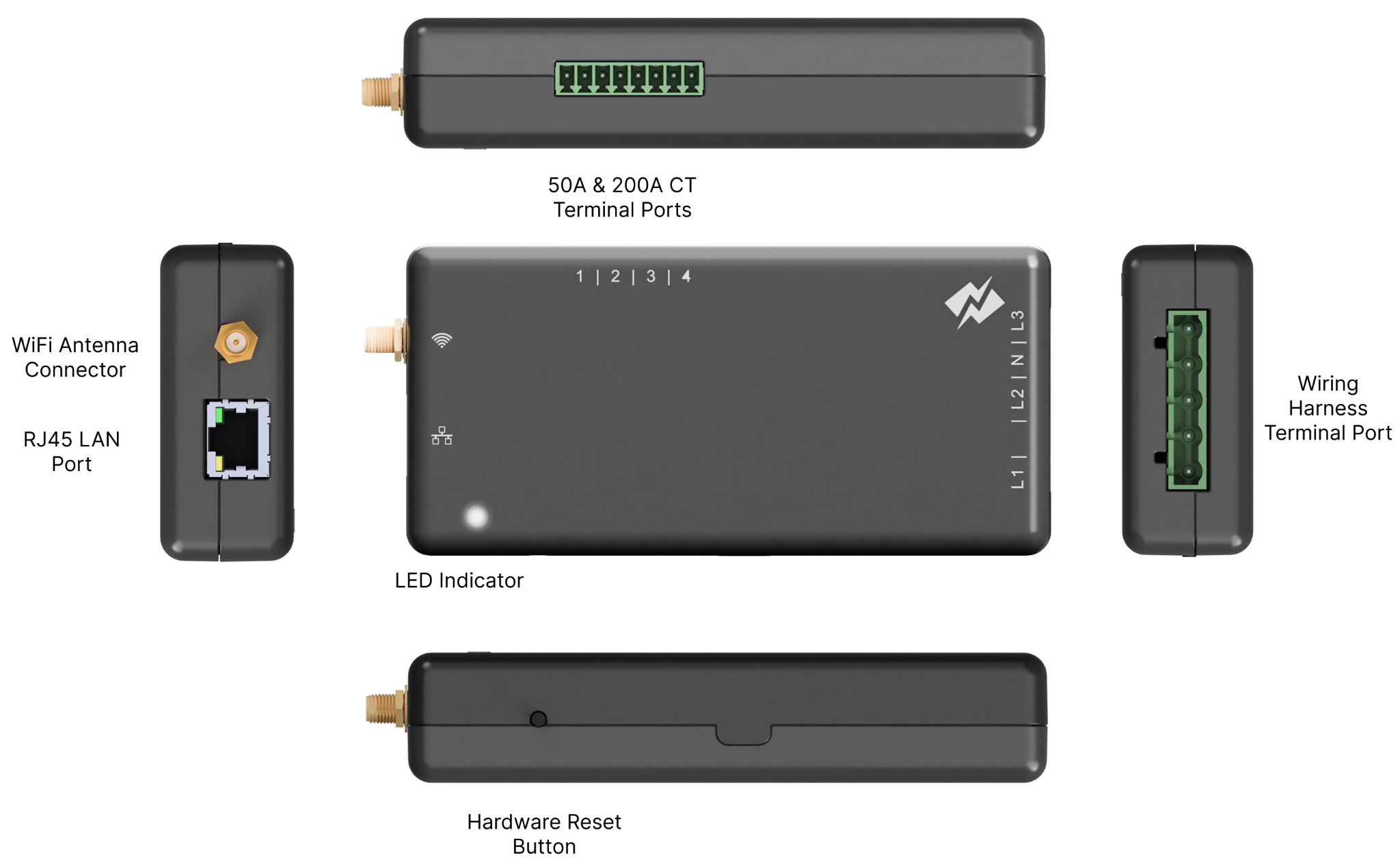
- Top: four sensor ports, numbered 1, 2, 3, 4.
- Right side: the voltage harness port (L1, L2, N, L3).
- Left side: the Wi-Fi antenna coax connector and the RJ45 Ethernet port.
- Front: the status light. See Status light.
- Bottom: the hardware reset button.
Port map

| Port | Sensor | Goes on |
|---|---|---|
| 1 | Main sensor (200 A CT or flex coil via integrator) | L1 of the breaker the EMS protects (L1 recommended, not required) |
| 2 | Main sensor (200 A CT or flex coil via integrator) | L2 of the same breaker |
| 3 | Branch 50 A CT | A battery or solar line, the Autel's second leg, or one other load |
| 4 | Branch 50 A CT | The EV charger (Autel), always |
Danger
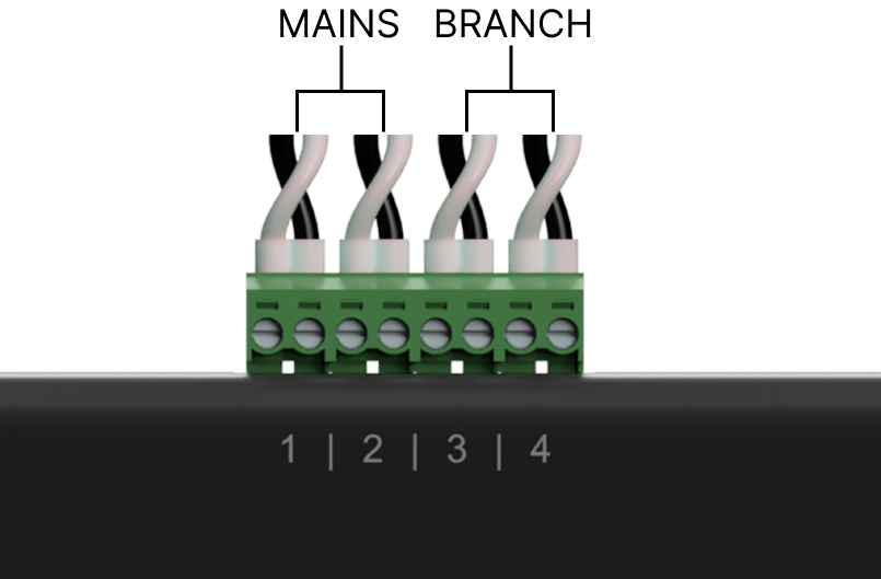
Ports 1 and 2 are mains only. The app enforces this. Never put a branch CT in port 1 or 2, or a main sensor in port 3 or 4. On one early install the swap made the charger read as the mains; the EMS paused charging every minute and it took a revisit to fix.
Voltage harness
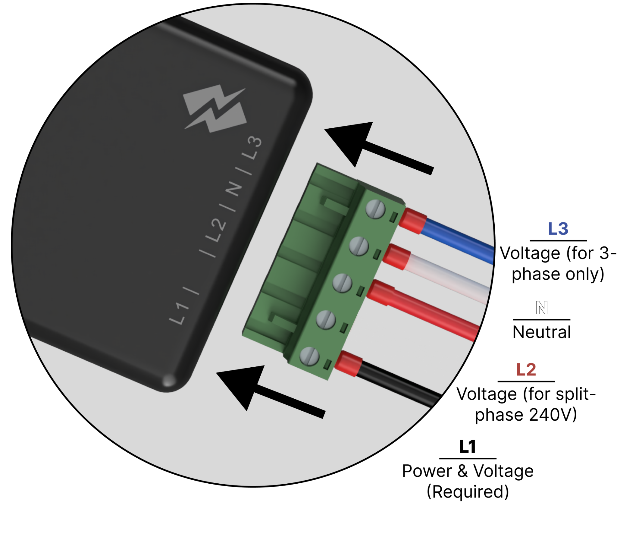
| Lead | Role | Connect to |
|---|---|---|
| Black (L1) | Powers the monitor and gives the voltage reference for phase A | Required on every install. A breaker pole |
| Red (L2) | Voltage reference for phase B (split-phase 240 V) | The other pole: the stacked breaker directly above or below, or the second pole of a 2-pole breaker. Leave it off only on a single-phase 120 V service |
| White (N) | Neutral | Required on every install. The neutral bus bar (except on an AFCI/GFCI breaker, see Step 5) |
| Blue (L3) | Third phase, or battery direction reference | 3-phase 208Y/120 V: the third phase. Split-phase: splice to L1 only when CT 3 monitors a battery. Otherwise cap it |
The Energy Monitor is Class II (double-insulated) and doesn't need a ground wire, so one slot on the voltage harness plug is empty.
Warning
L2 and L3 are voltage sensing only. Connect them to hot (line) conductors only, never to neutral.
Something wrong or unclear on this page? Email support@getneocharge.com. Rev 005 is the controlled copy.
