




Energy Monitor + EMS Installer Guide
Wiring diagrams by site
Find the case that matches the home, then place CT 1–4 and set the app exactly as that case shows.
Every home in the pilot gets one new Autel. Find the case below that matches the panel layout, then follow it for sensor placement, app settings and commissioning. Any EV charger already on site is an existing load. It stays in the load calc and needs no sensor.
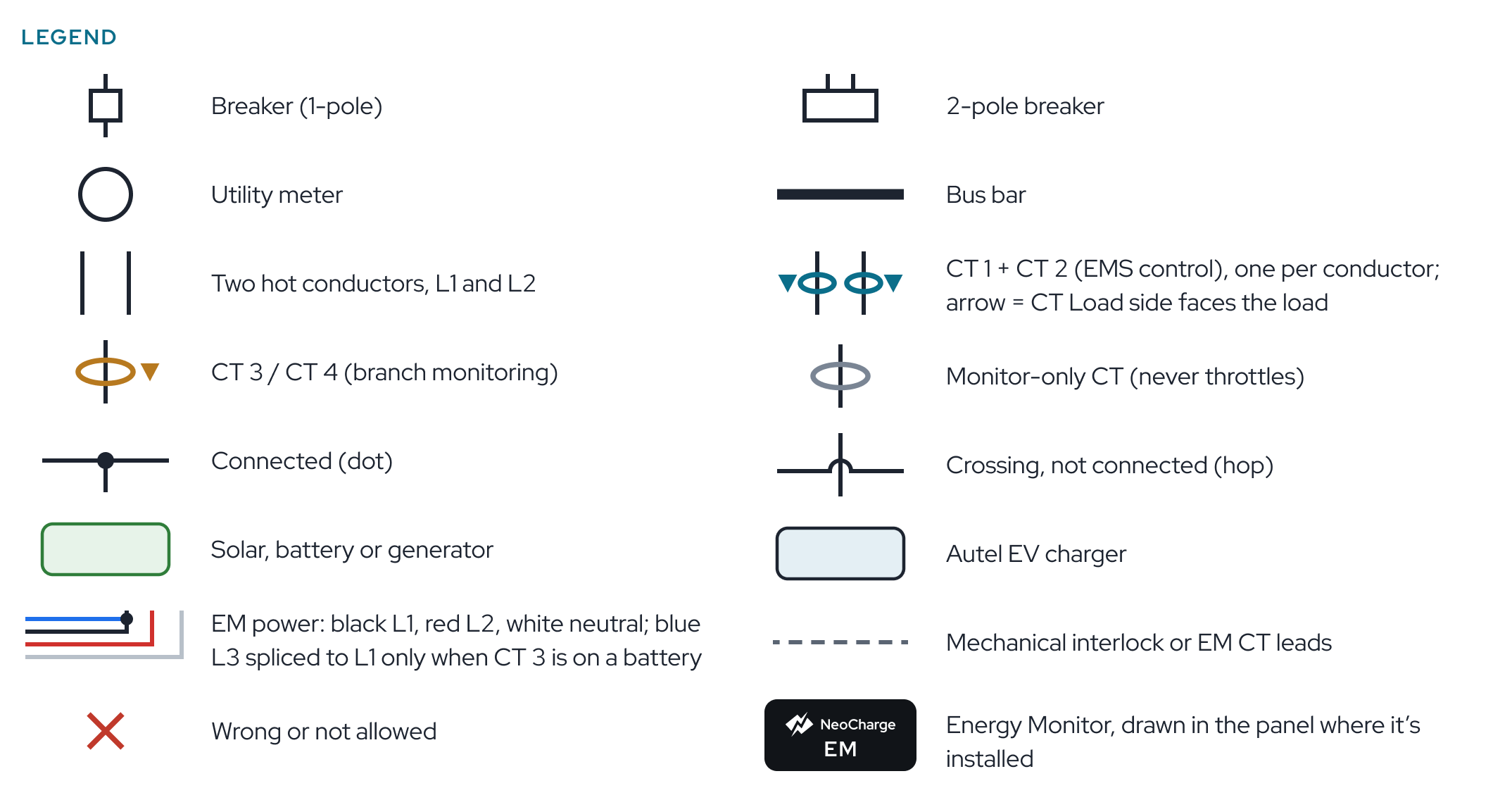
The diagrams are one-line drawings. Each hot conductor that carries CT 1–2 is drawn separately (L1 and L2). Branch circuits are drawn as a single line.
Diagram index
Pick the group that matches the equipment on site, then the case. Each card links to the full diagram and setup.
Battery, with or without solar
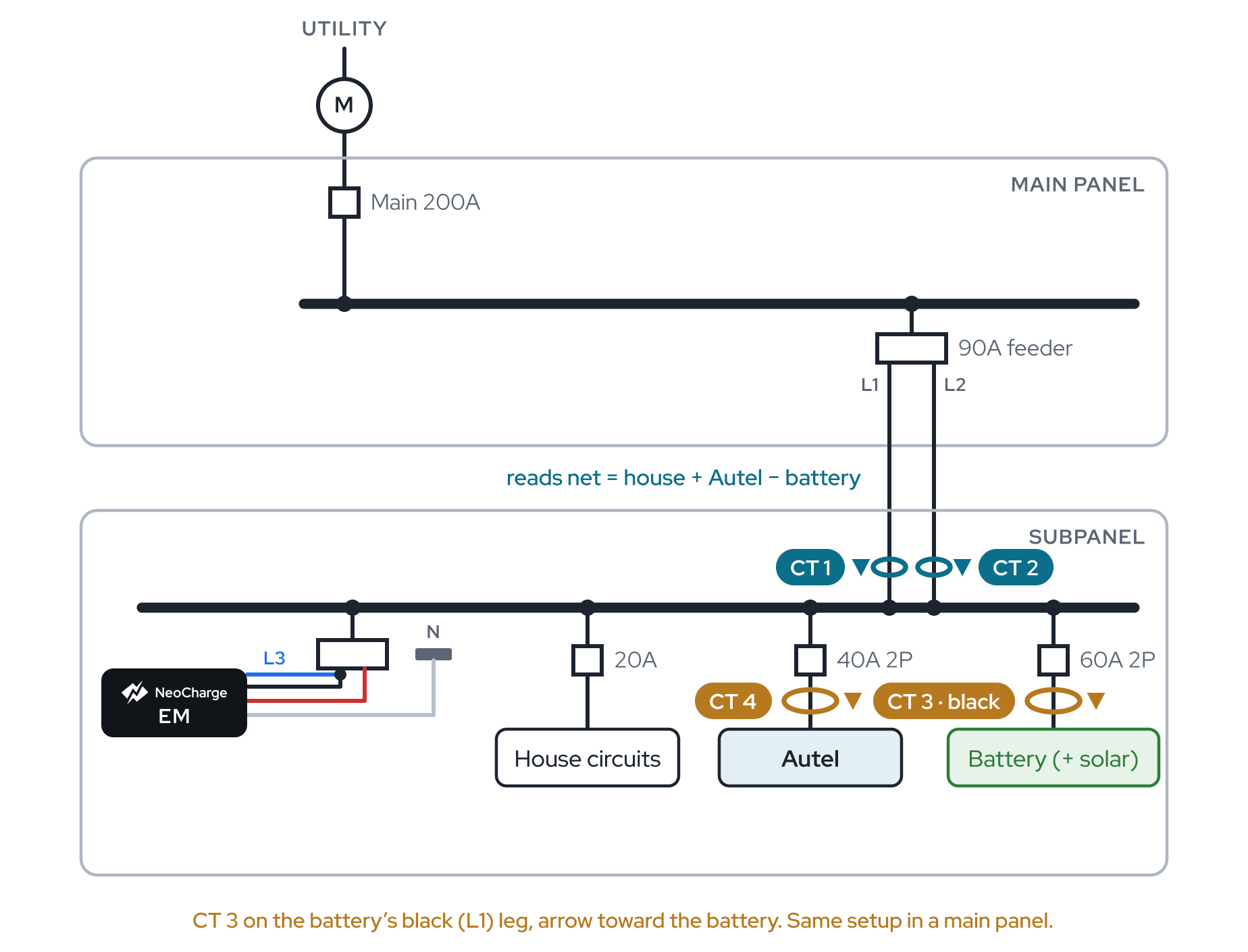 Battery backfed in the Autel's panel
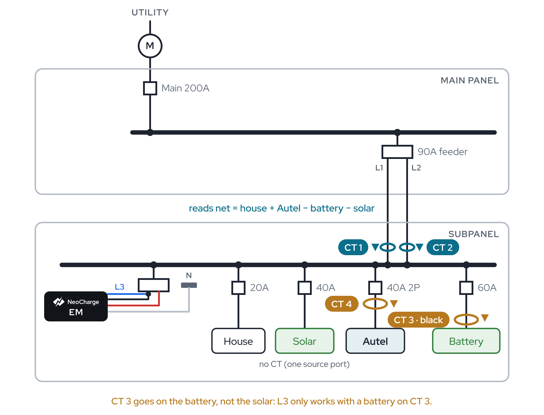 Battery and solar on separate breakers
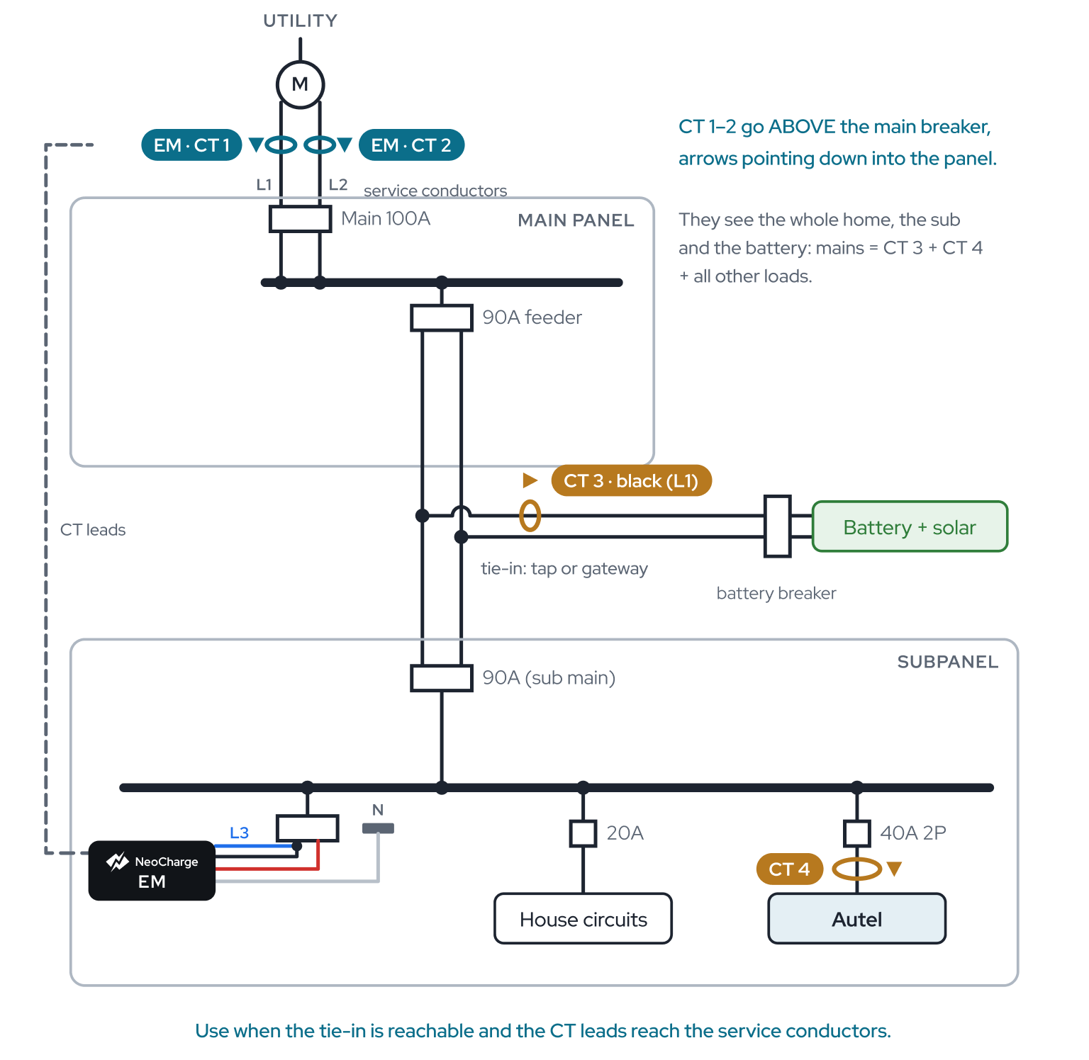 Battery tie-in, mains upstream
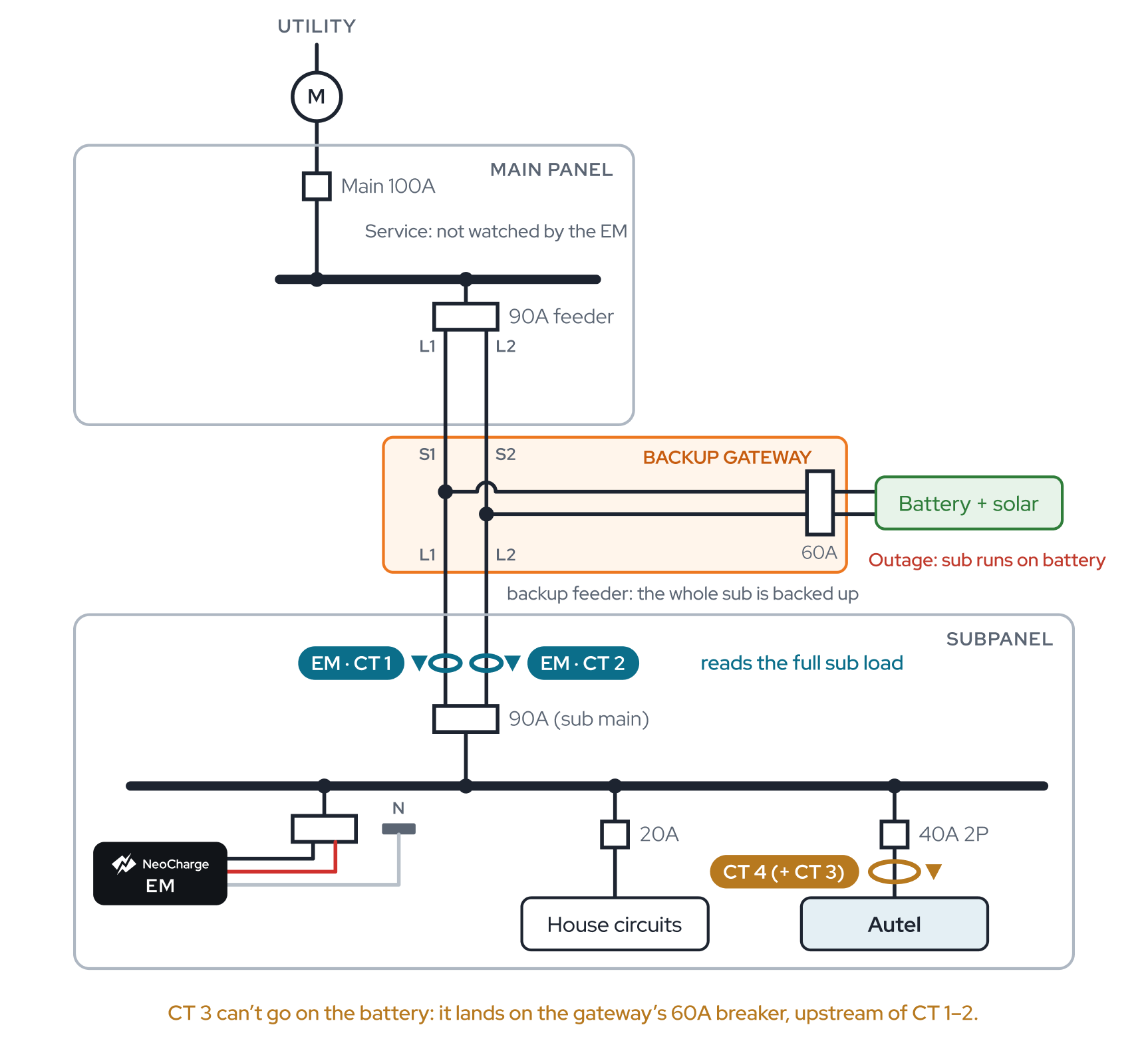 Battery in a backup gateway, mains on the sub
 Battery in a backup panel, Autel in main
 Source in the main panel, Autel in a subpanel also listed under Solar
 Line-side (supply-side) tap also listed under Solar
The rules that apply to every case
- CT 1 and CT 2 go on both hot conductors of the breaker the EMS protects. Clamp them just above or just below that breaker, one per leg. Nothing may be tapped in between. The EMS limit is that breaker's rating.
- Every CT arrow points toward the load. Split-core CTs and flex coils alike.
- Ports 1–2 are mains only. The app enforces this. Never put a branch sensor in port 1–2 or a mains sensor in port 3–4. Port 1 on L1 is recommended.
- CT 4 always goes on the Autel.
- CT 3 is the only port for a battery or solar line. With no source on site, CT 3 is the homeowner's choice: - the Autel's second leg (app: One 240V circuit), or - one other load they want to see (app: Two different circuits).
- CT 3 and CT 4 must sit downstream of CT 1–2. The mains have to add up to at least CT 3 + CT 4 + every other load. A source that joins upstream of CT 1–2 never gets CT 3.
- On a battery or solar line, the battery or inverter is the load. Point CT 3's arrow toward it. The app shows a negative value while it exports or produces.
- Battery on CT 3: clamp the battery's black (L1) conductor, arrow toward the battery. Splice the EM's blue L3 onto its black L1 on the same EM breaker (splice kit). CT 3 then reads charging and discharging with opposite signs: negative when the battery discharges or exports.
- No battery on CT 3: cap the blue L3. Solar alone never needs L3.
- EM power: black L1 + red L2 on a 2-pole breaker (or two vertically adjacent single-pole breakers), white neutral to the neutral bar.
- A source inside the protected panel makes CT 1–2 read net (loads minus the source). That is correct: it is what the protected breaker carries.
- The EMS limits on CT 1–2 only. A source CT on CT 3 is for monitoring. It is never added into the control math, so it can't make up for mains sensors that miss part of the load.
- Commission with every source idle: at night, with the inverter off, or with the battery set to backup-only for a few minutes. Run a test charge and confirm the sign: the mains rise by about the charger amps, with positive kW.
- Panel rating in the app is 100% of the protected breaker: the main breaker for Main panel, the feeder breaker for Subpanel. The installer PIN locks it.
- Don't cut, shorten, splice or extend sensor leads. Coil and tie off the excess. If the leads won't reach the conductors a case calls for, use that case's fallback or call NeoCharge install support.
Warning
Reversed mains sensors make import look like export, so the EMS may never throttle. With a battery or solar on site, midday negative readings are normal and look exactly like reversed sensors. Always check the sign with a test charge while the sources are idle.
Find your case
Work down the questions and stop at the first one that matches.
- Are both the service and the Autel's subpanel over their load calc? Go to B1.
- Is the service split into two disconnects (for example, two 200 A) with no single main? Go to B2.
- Is there a generator through an interlocked breaker? Go to A11.
- Would the Autel land in a critical-loads panel fed by a hybrid inverter's backup output? Go to A12.
- No solar and no battery? - Autel in the main panel: A1. - Autel in a subpanel: A2. - An EV charger already on the main panel, Autel added in a subpanel: A8.
- Solar or battery on a line-side (supply-side) tap between the meter and the main breaker? Go to A10.
- Solar or battery in a different panel from the Autel (source in the main panel, Autel in a subpanel)? Go to A4.
- Source in the same panel as the Autel? - Solar only: A3. - Battery (with or without solar) on one backfed breaker: A5. - Battery and solar on separate breakers: A6.
- Battery tied in on the feeder between two breakers (a tap or gateway between the main panel and the Autel's subpanel)? - A backup gateway whose backup output feeds the whole subpanel: A7b. - A tap that's reachable, and the CT leads reach the service conductors above the main breaker: A7a. - Otherwise: A7b.
- Battery in a downstream backup load center (partial-home backup)?
Still no match? Stop and call NeoCharge install support at +1 888 944 5581 with photos of the meter, the main panel and every subpanel.
No solar or battery
The home has no solar and no battery. These are the most common installs.
A1: No solar, Autel in the main panel
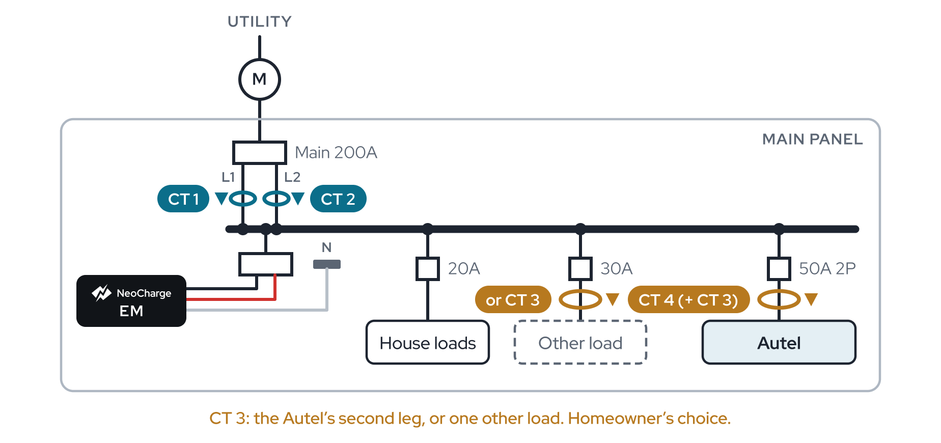
When it applies: no solar, no battery. The Autel lands in the main panel.
- CT 1–2: the main breaker's load-side conductors, L1 and L2, arrows toward the bus.
- CT 3: the Autel's second leg, or one other load in the panel (homeowner's choice).
- CT 4: the Autel, one leg.
- L3: capped.
- App settings: Main panel, main breaker rating (for example 200 A). Sensors: One 240V circuit if CT 3 is on the Autel, Two different circuits if CT 3 is on another load.
- Commissioning: test charge. The mains rise by about the charger amps, positive kW.
- Status: Supported.
A2: No solar, Autel in a subpanel
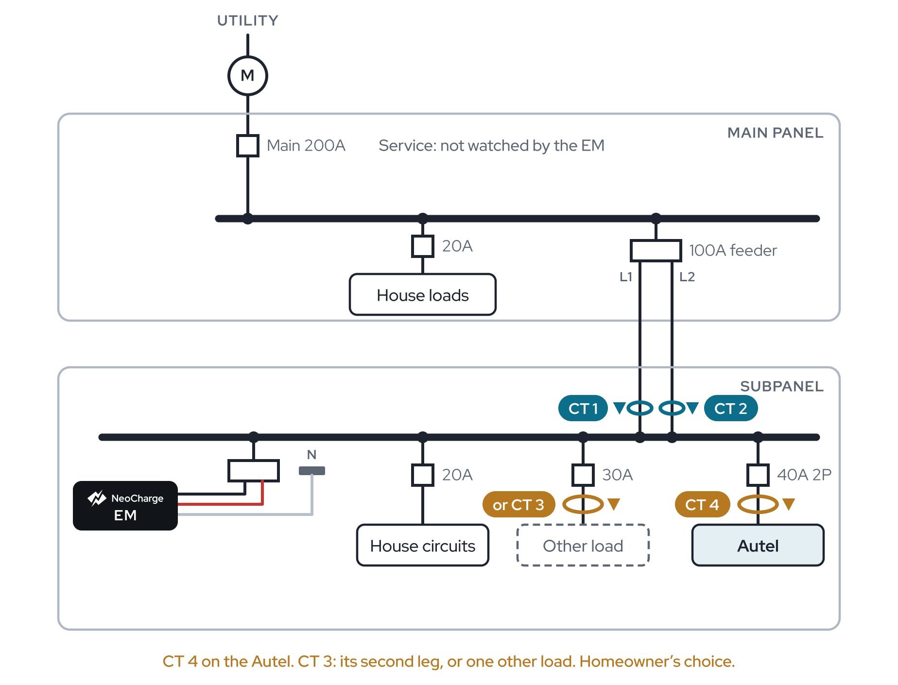
When it applies: no solar, no battery. The Autel lands in a subpanel.
- CT 1–2: the subpanel feeder conductors at the sub lugs, arrows toward the sub.
- CT 3: the Autel's second leg, or one other load in the subpanel.
- CT 4: the Autel.
- L3: capped.
- App settings: Subpanel, feeder breaker rating. Sensors as in A1.
- Commissioning: test charge, mains rise by about the charger amps.
- Status: Supported. The EM does not watch the service, so the service must pass a load calc on its own. If it doesn't, see B1.
Note
Outdoor meter-main with nothing else on it. The feeder entering the interior panel carries exactly what the meter-main breaker carries. Put CT 1–2 on those feeders and use the meter-main breaker rating with Main panel. If the meter-main also feeds other loads or a source, the interior feeder misses them, and the service has to pass a load calc on its own. Meter-mains usually need the flex kit; see Rogowski (flex) sensors.
A8: Existing EV charger on the main panel, Autel added in a subpanel
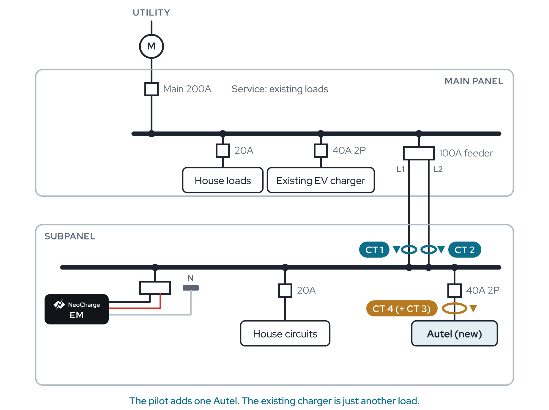
When it applies: the home already has an EV charger in the main panel and the new Autel goes in a subpanel.
- CT 1–2: the sub feeder at the sub lugs, arrows toward the sub.
- CT 3: the Autel's second leg, or another load in the subpanel.
- CT 4: the Autel.
- L3: capped.
- App settings: Subpanel, feeder breaker rating. Sensors as in A1.
- Commissioning: test charge, mains rise by about the charger amps.
- Status: Supported. The existing charger is part of the service load calc and needs no sensor. If the service fails the load calc with both chargers, the service is constrained too: see B1.
Solar, no battery
Solar on site, no battery. Solar never needs L3.
A3: Solar only, backfed in the Autel's panel
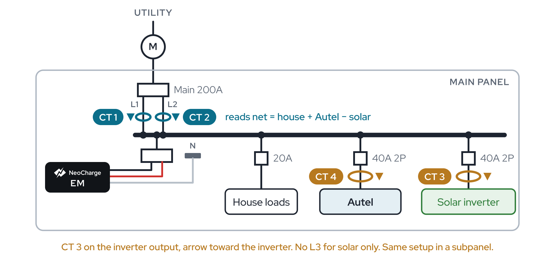
When it applies: solar with no battery, on a backfed breaker in the same panel as the Autel (main panel or subpanel).
- CT 1–2: the protected panel's main breaker (or its feeder, if the Autel is in a subpanel), load side, arrows toward the load. They read net (loads minus solar), which is what that breaker carries.
- CT 3: the solar inverter output, one leg, arrow toward the inverter.
- CT 4: the Autel, one leg.
- L3: capped. Solar alone doesn't need it.
- App settings: Main panel or Subpanel with that breaker's rating. Sensors: Two different circuits, with CT 4 as the EV charger.
- Commissioning: at night or with the inverter off. Test charge, mains rise by about the charger amps.
- Status: Supported.
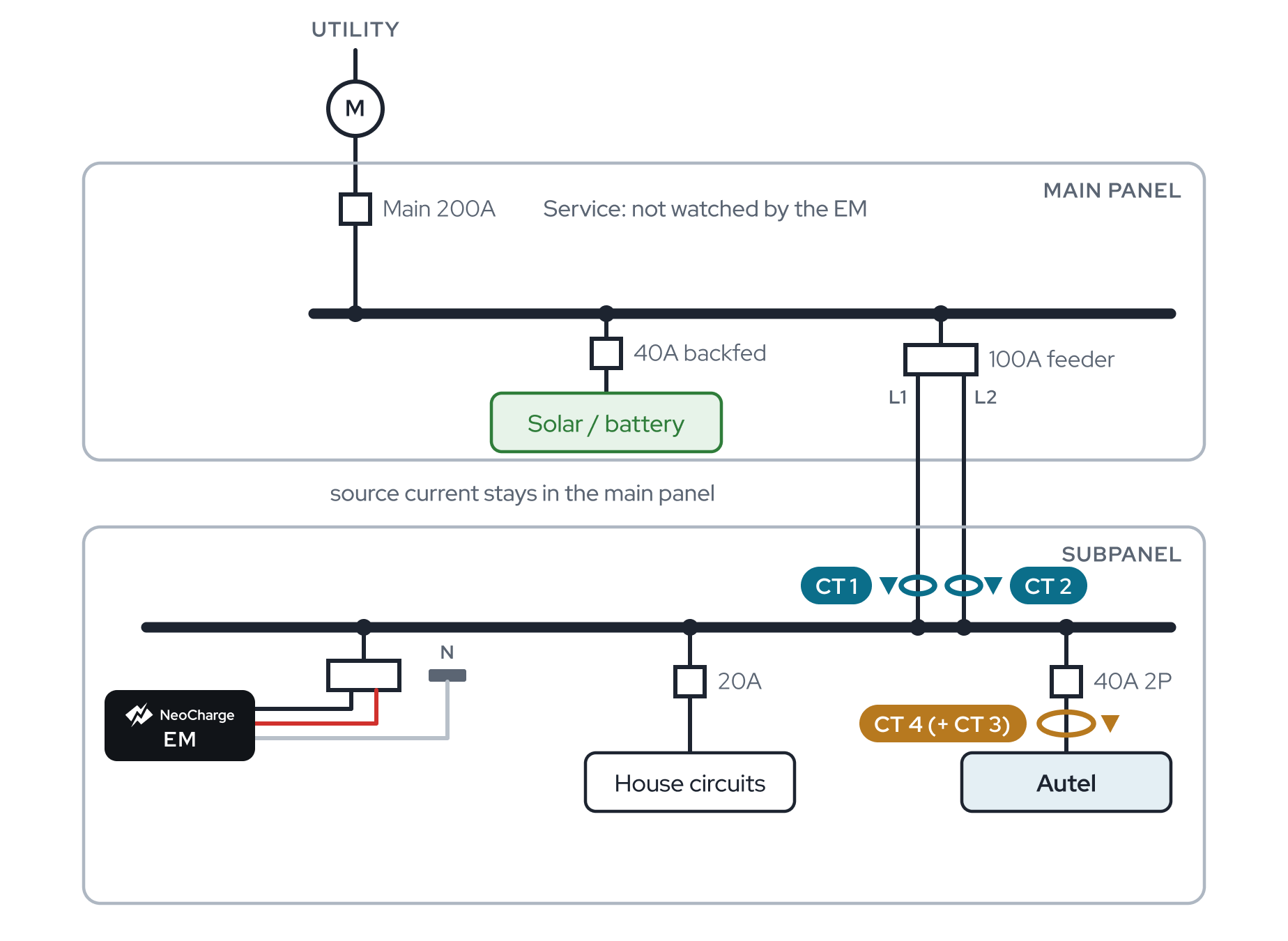
A4: Solar or battery in the main panel, Autel in a subpanel
When it applies: the solar or battery is in the main panel and the Autel is in a subpanel. No source current flows through the sub feeder.
- CT 1–2: the sub feeder at the sub lugs, arrows toward the sub. They read the gross sub load.
- CT 3: the Autel's second leg, or another load in the subpanel. The source is in another panel and stays unmonitored.
- CT 4: the Autel.
- L3: capped. CT 3 can't reach the source here.
- App settings: Subpanel, feeder breaker rating. Sensors as in A1.
- Commissioning: test charge, mains rise by about the charger amps.
- Status: Supported. The service must pass a load calc on its own.
Note
With a battery and a backup device, the whole home may island in an outage. The battery's backup output is then the real limit.
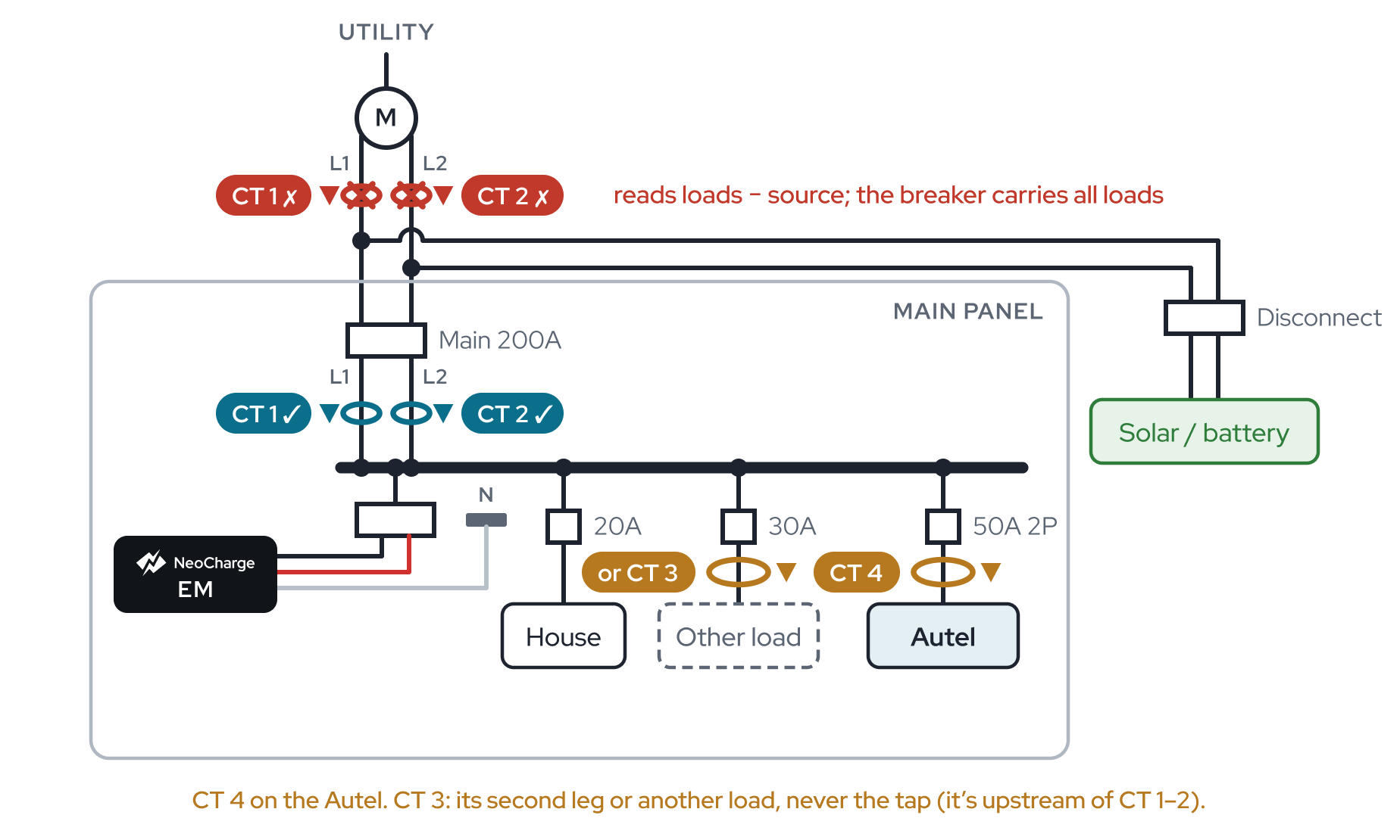
A10: Solar or battery on a line-side (supply-side) tap
When it applies: the solar or battery ties onto the service conductors between the meter and the main breaker, usually through its own fused disconnect. The EMS protects the service.
- CT 1–2: below the tap, either between the tap and the main breaker or just below the main breaker (as drawn), arrows toward the load. Never on the service conductors above the tap. Above the tap the sensors read loads minus the source while the main breaker carries every load, so the EMS reads low and won't protect the main.
- CT 3: the Autel's second leg, or another load. Never on the tap conductors: the tap is upstream of CT 1–2.
- CT 4: the Autel.
- L3: capped. CT 3 can't be on the battery here.
- App settings: Main panel, main breaker rating. Sensors as in A1.
- Commissioning: confirm where the tap is before you clamp anything. Then run a test charge: mains rise by about the charger amps.
- Status: Supported, with a placement trap.
Warning
A battery on a supply-side tap always comes with a backup device at the meter. In an outage the battery's backup output is the limit.
Battery, with or without solar
A battery is on site. CT 3 goes on the battery's black (L1) conductor with L3 spliced to L1, unless the case says otherwise.
Battery in a different panel from the Autel, or on a line-side tap: see A4 and A10. They cover solar and battery.
A5: Battery (with or without solar) backfed in the Autel's panel
When it applies: a battery, with or without solar on its own inverter, on one backfed breaker in the same panel as the Autel (main panel or subpanel).
- CT 1–2: the protected panel's feeder (or main breaker, if the Autel is in the main panel). They read net (loads minus battery), which is what that breaker carries.
- CT 3: the battery breaker's black (L1) conductor, arrow toward the battery. It reads negative when the battery discharges or exports.
- CT 4: the Autel, one leg.
- L3: spliced to black L1 on the EM's breaker (splice kit).
- App settings: Main panel or Subpanel with the protected breaker's rating. Sensors: Two different circuits, with CT 4 as the EV charger.
- Commissioning: with the battery idle (at night, or set to backup-only for a few minutes). Test charge, mains rise by about the charger amps.
- Status: Supported.
Note
If a backup device sits upstream (a meter-collar backup switch or a whole-home gateway), the panel islands in an outage and the battery's backup output becomes the limit. The CT setup doesn't change.
A6: Battery and solar on separate breakers in the Autel's panel
When it applies: the battery and the solar each have their own breaker in the Autel's panel. This is common when a battery is added to existing solar. If the solar runs through the battery's own inverter (one breaker), use A5.
- CT 1–2: the protected panel's feeder (or main breaker). They read net (loads minus battery minus solar).
- CT 3: the battery breaker's black (L1) conductor, arrow toward the battery. The solar breaker gets no sensor: CT 3 is the only source port, and the battery needs it for L3.
- CT 4: the Autel, one leg.
- L3: spliced to black L1 on the EM's breaker.
- App settings: as A5.
- Commissioning: at night, or with the battery set to backup-only and the solar off. Test charge, mains rise by about the charger amps.
- Status: Supported.
A7a: Battery tied in between two breakers, mains upstream
When it applies: the battery (often with solar) joins the feeder between the main panel's feeder breaker and the subpanel's main breaker, through a tap or a gateway. The giveaway is two breakers of the same size on one feeder (for example 90 A at each end). Use A7a when you can reach the tie-in and the CT leads reach the service conductors. This gives the most data.
- CT 1–2: the service conductors just above the main breaker (between the meter and the main), one per leg, arrows pointing down into the main panel. Nothing may be tapped between the sensors and the main. They see the whole home, the sub and the battery.
- CT 3: the battery's black (L1) conductor between the tie-in and the battery breaker, arrow toward the battery.
- CT 4: the Autel, one leg.
- L3: spliced to black L1 on the EM's breaker.
- App settings: Main panel, main breaker rating. Sensors: Two different circuits, with CT 4 as the EV charger.
- Commissioning: with the battery idle. Test charge, mains rise by about the charger amps.
- Status: Supported. The EMS protects the main breaker. The subpanel's own breakers must pass a load calc on their own; if they don't, call NeoCharge install support before installing.
Note
If the tie-in is a backup gateway, the panel islands in an outage and the battery's backup output becomes the limit.
A7b: Battery in a backup gateway between the main panel and the sub
When it applies: a backup gateway sits between the main panel's feeder breaker and the subpanel. Its supply terminals (S1/S2) are fed from the main panel, the battery and solar land on a breaker inside the gateway, and its backup output (L1/L2) feeds the subpanel, so the whole sub is backed up. Also use A7b for a feeder tap when A7a isn't possible: the tie-in can't be reached, the CT leads won't reach the service conductors, or it's a hard bus connection.
- CT 1–2: the gateway's backup feeder at the subpanel's main breaker, one per leg, arrows toward the sub. They read the full sub load, from the grid or the battery, which is what that breaker carries.
- CT 3: not on the battery. The battery joins inside the gateway, upstream of CT 1–2, so the mains wouldn't include it. Use the Autel's second leg or another sub load.
- CT 4: the Autel.
- L3: capped.
- App settings: Subpanel, rating of the subpanel's main breaker (the breaker CT 1–2 surround). Sensors as in A1.
- Commissioning: test charge with the battery idle or set to backup-only. The mains rise by about the charger amps and read positive.
- Status: Supported. The battery goes unmonitored, and the EM can't see the gateway's supply side, so whole-home grid exchange isn't measured. The service must pass a load calc on its own.
Note
In an outage the gateway islands and the whole sub runs on the battery, so the battery's backup output becomes the limit.
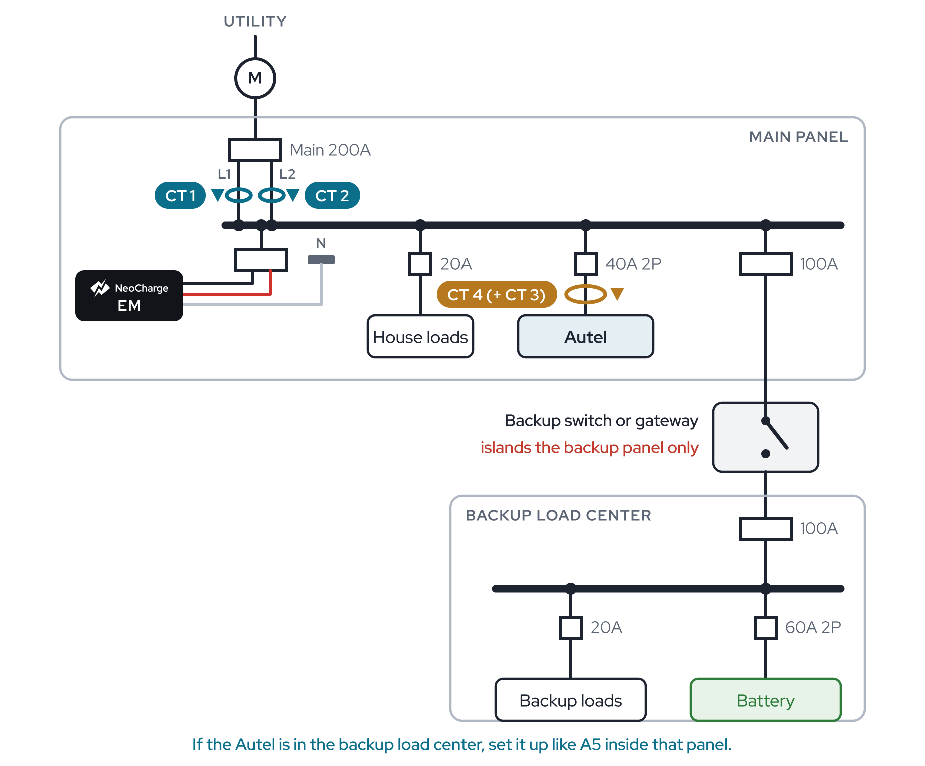
A9: Battery in a downstream backup panel, Autel in the main panel
When it applies: partial-home backup. A feeder from the main panel runs through a backup switch or gateway to a backup load center that holds the battery. The Autel is in the main panel.
- CT 1–2: the main breaker's load side, arrows toward the bus. The battery is downstream through the feeder, so they read net.
- CT 3: the battery's black (L1) conductor, arrow toward the battery, but only if the CT 3 lead reaches the backup load center without extending it. Otherwise use the Autel's second leg or another load.
- CT 4: the Autel.
- L3: spliced to black L1 only if CT 3 is on the battery; otherwise capped.
- App settings: Main panel, main breaker rating. Sensors: Two different circuits with CT 3 on the battery or another load; One 240V circuit with CT 3 on the Autel.
- Commissioning: with the battery idle. Test charge, mains rise by about the charger amps.
- Status: Supported. The Autel here is not backed up, so it is off during an outage.
Tip
The battery system's own sensors are often already on the main-panel conductors. Clamp ours beside them.
If the Autel goes in the backup load center instead, set it up like A5 inside that panel.
Generator, backup panels and two-panel sites
Check these before installing. Two-monitor sites (B1 and B2) are supported. The others need a call to NeoCharge install support first.
A11: Generator through an interlocked breaker
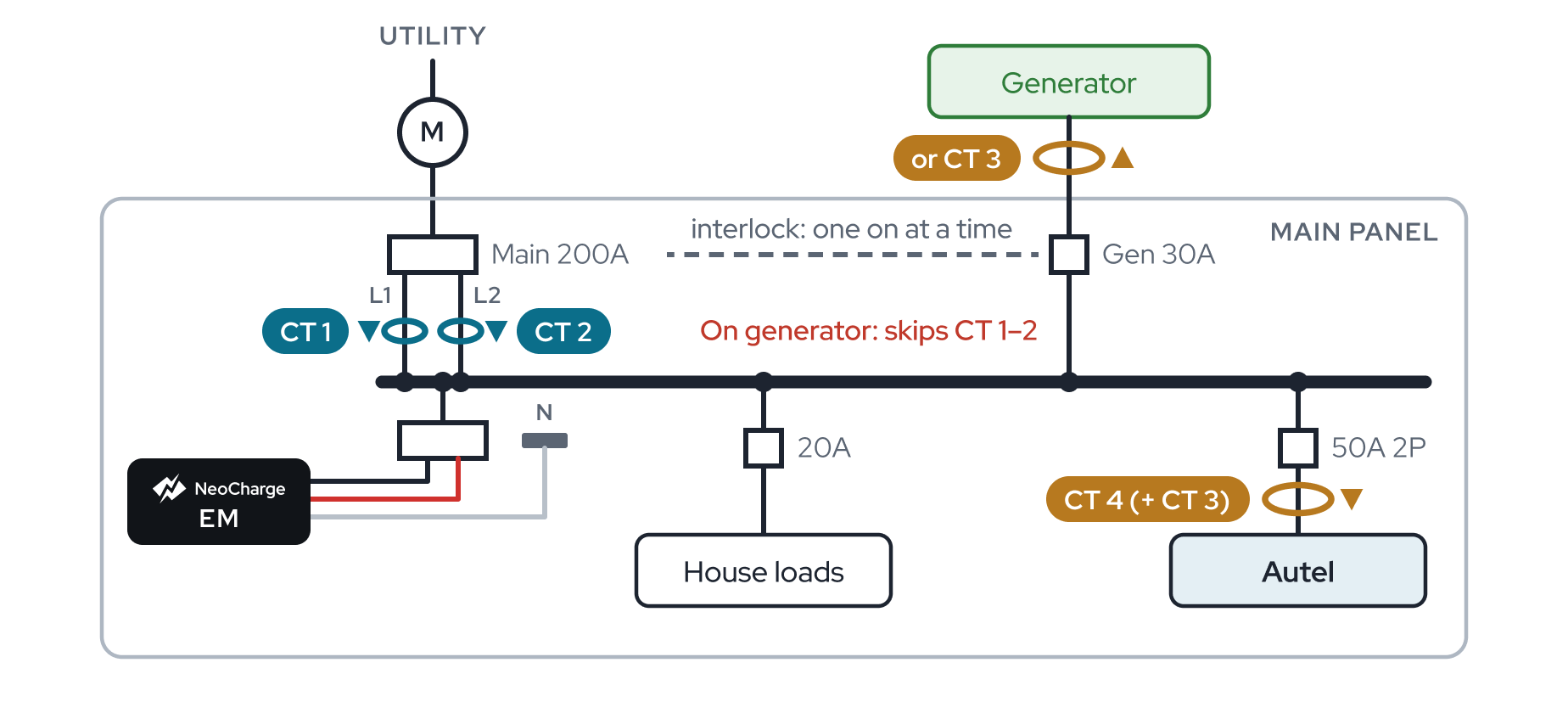
When it applies: a portable or standby generator backfeeds the panel through a breaker with a mechanical interlock against the main.
Why it's blocked: on generator power, current never passes CT 1–2. The EMS reads near zero and won't throttle the Autel against the generator's output.
Status: Blocked.
Danger
Stop. Don't install the EMS on a site with an interlocked generator until NeoCharge confirms the setup. Call NeoCharge install support at +1 888 944 5581 with photos of the panel, the interlock and the generator inlet. Support will check whether the Autel can sit on a circuit the generator doesn't feed.
A12: Autel in a critical-loads (backup) panel
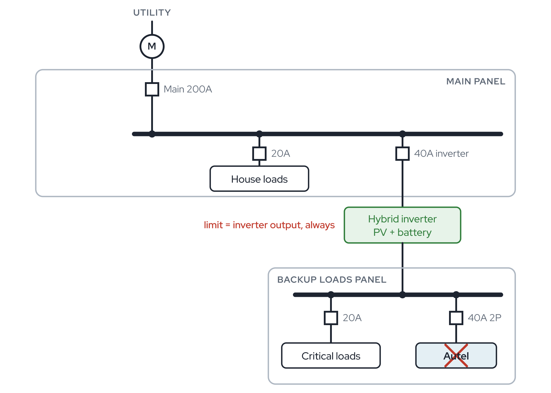
When it applies: a hybrid inverter (PV + battery) feeds a critical-loads panel from its backup output, and the Autel would land in that panel. The limit there is always the inverter's continuous output, on grid and off.
Status: Do not install.
Danger
Don't install the Autel in a critical-loads panel. Move it to the main panel (A1 or A3) or to a subpanel that isn't backed up. If neither is possible, stop and call NeoCharge install support at +1 888 944 5581.
B1: Service and subpanel both constrained
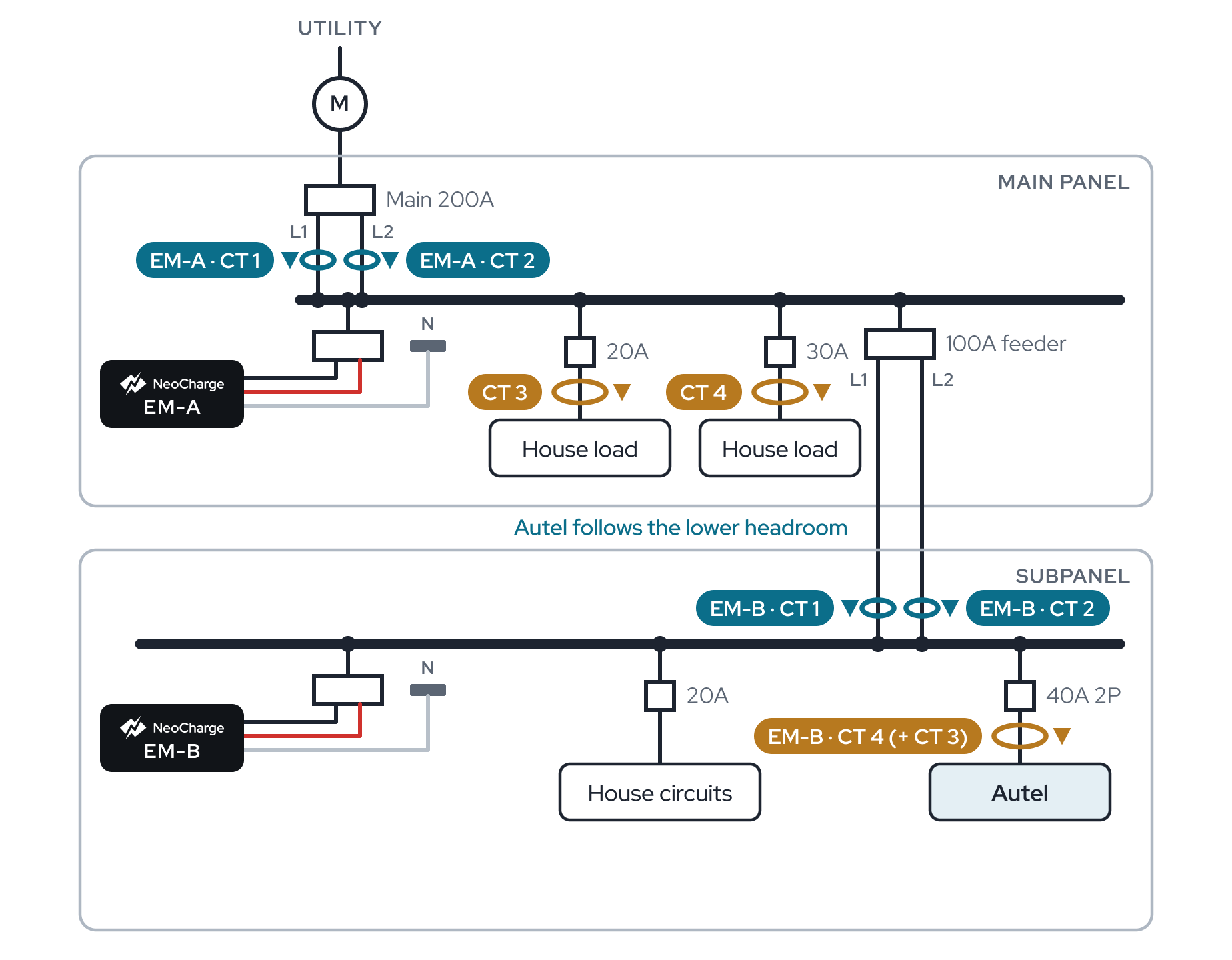
When it applies: the Autel goes in a subpanel, and both the service and the subpanel fail the load calc with the Autel added. Protecting both would take two EMs (EM-A on the main, EM-B on the sub feeder) controlling one Autel.
Status: Supported with two Energy Monitors.
Install EM-A in the main panel, set up as A1 with the main breaker rating, and EM-B in the subpanel, with CT 1–2 on the sub feeder and CT 4 on the Autel. See Two Energy Monitors and EMS setup. The charging limit follows whichever panel has less headroom.
B2: Split service, two disconnects
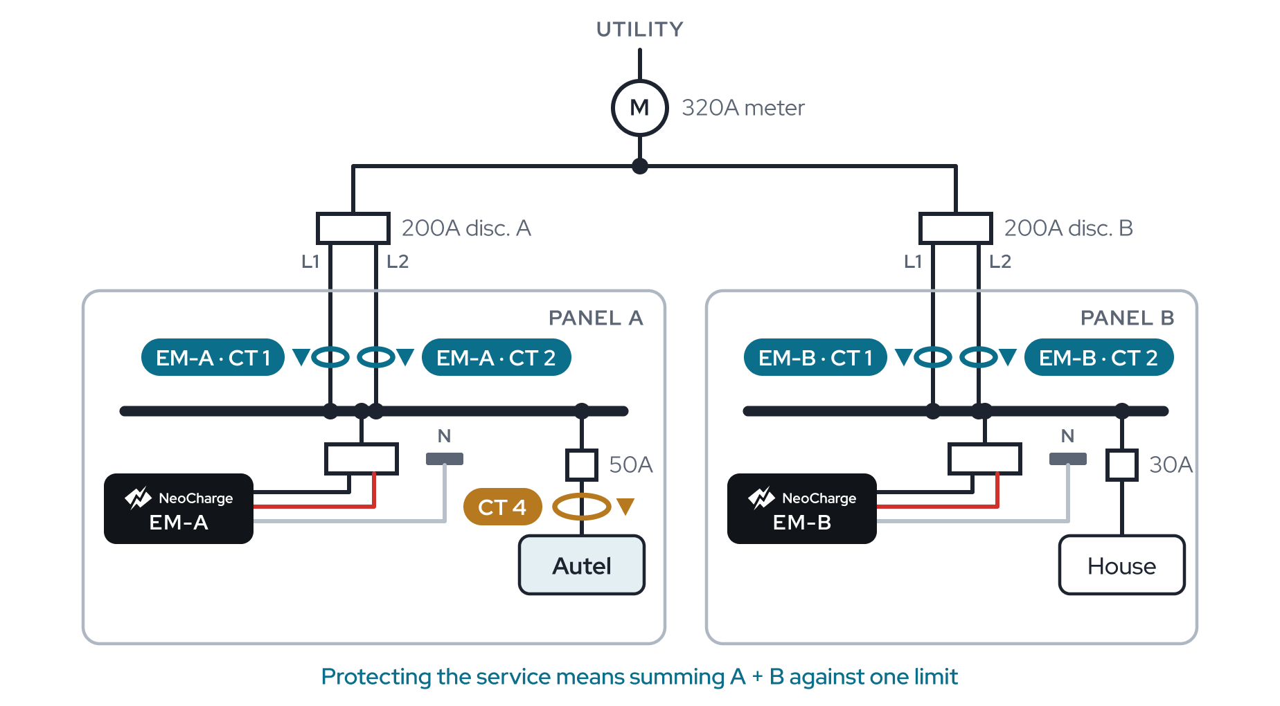
When it applies: the meter feeds two service disconnects (for example two 200 A) with no single main breaker. Protecting the service means summing both feeders against one limit.
Status: Supported with two Energy Monitors.
Install one Energy Monitor in each panel, with CT 1–2 on that panel's feeder conductors from its disconnect. CT 4 goes on the Autel in whichever panel it's in. Set up both monitors as in Two Energy Monitors and EMS setup.
Something wrong or unclear on this page? Email support@getneocharge.com. Rev 005 is the controlled copy.
