





Guide de l'installateur Energy Monitor + EMS
Installer l’Energy Monitor
Step-by-step hardware install of the Energy Monitor, voltage harness, internet connection and all four sensors, with split-core and flex variants.
This is Step 3 of the EMS setup. Start the Autel firmware update first (see Before you go) and do this install while it runs.
Before you start, pick the site case in Wiring diagrams. It shows where the monitor and every sensor go for that site.
Step 1: Photograph the back label

- Before the monitor goes in the panel, photograph its back label on the homeowner's phone. The label has the serial number and the 6-digit installer PIN.
- Keep the photo. You enter the PIN at the end of Set Up Energy Management, and it's one of the required closeout photos.
Note
The installer PIN is not the Autel charger PIN. The charger PIN is in the Autel Quick Start booklet.
Step 2: Turn off the main breaker and remove the cover
- Confirm the Autel firmware update has finished, or isn't due to start.
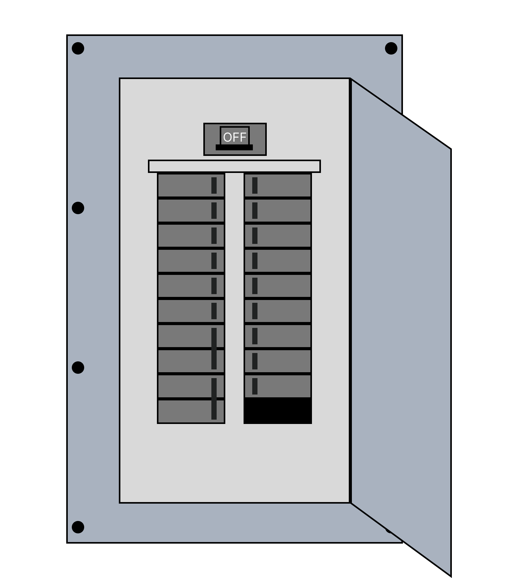
- Turn off the service disconnect and/or main breakers feeding the panel. The disconnect may be outside this panel.
- Remove the cover screws and the cover.
Danger
⚡ DANGER: The service mains are energized! They stay live with the main breaker off.
Step 3: Mount the monitor

- Mount the monitor in the panel whose load it manages. That is usually the panel the Autel breaker is in, and it can be a subpanel.
- Keep it at least 50.8 mm (2 in) from live parts: primary conductors, primary terminals and primary lugs. Insulated cables are fine.
- Mounting it to the grounded enclosure near the neutral bar is fine. Don't let it touch the panel's interior insulation, and never attach it to an energized part.
- Leave the side ports reachable until the harness and antenna are connected.
Split-core CT kit
Nothing else mounts in the panel.
Flex (Rogowski) kit
Also plan space for the sensor power supply and the two integrators, inside the panel near the monitor, with the same 2 in (50.8 mm) clearance from live parts. See Mount the power supply and integrators.
Step 4: Plug in the voltage harness
- Push the harness's green screw-terminal plug into the port on the right side of the monitor until it clicks.
- The 16 AWG harness leads can be cut to length to reduce clutter. (This applies to the voltage harness only. Never cut sensor leads.)
Lead roles are in the harness table. In short: black L1 and white N on every install, red L2 on split-phase, and blue L3 spliced to L1 when CT 3 monitors a battery (or on the third phase of a 3-phase service). Otherwise cap blue.
Step 5: Wire power to the monitor
The monitor draws less than 50 mA. With the flexible kit, the monitor and sensor power supply together draw less than 1.5 A.
Pick a supply breaker:
- Two vertically adjacent (stacked) single-pole breakers, or one 2-pole breaker, so L1 and L2 are on opposite legs.
- An empty breaker or a splice into an in-use breaker are both fine.
- Any rating works if the splice wire gauge matches the circuit wire and meets code. 15 A is typical.
- Wire to the breaker closest to the monitor where you can.
Then wire it one of three ways.
Note
Battery on CT 3? Blue L3 joins the black L1.
If CT 3 monitors a battery, splice blue (L3) to black (L1) in the same L1 connection, on the same breaker. L3 is CT 3's voltage reference: without it, the monitor can't tell the battery charging from discharging. Each of 5a, 5b and 5c below shows where L3 goes.
- Main use, battery on CT 3: splice L3 to L1.
- Only other use, 3-phase 208Y/120 V: land L3 on the third phase.
- Anything else: cap L3.
5a. Empty breakers
Split-core CT kit
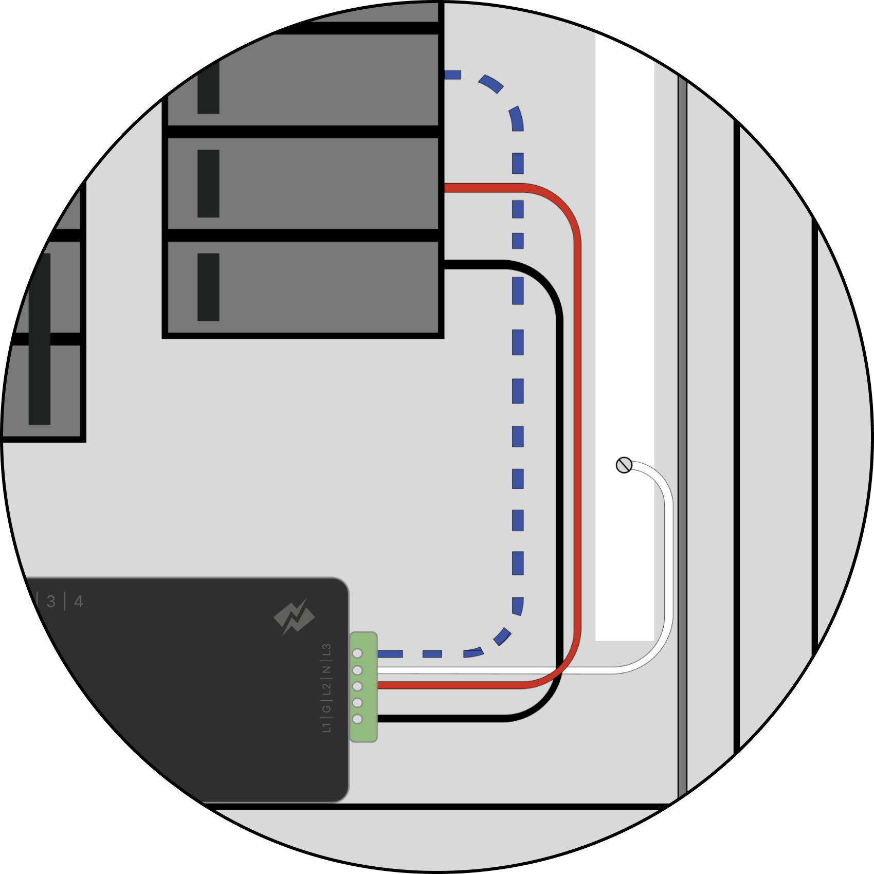
- Land white (N) on the neutral bus bar.
- Turn off the two stacked breakers (or the 2-pole). Land black (L1) on one pole and red (L2) on the other.
- Blue (L3):
- Battery on CT 3: join black (L1), blue (L3) and a splicing wire with a wire nut. Land the splicing wire on the L1 pole in place of black.
- 3-phase: land blue on the third phase (Blue L3).
- Otherwise: cap blue.
Flex (Rogowski) kit
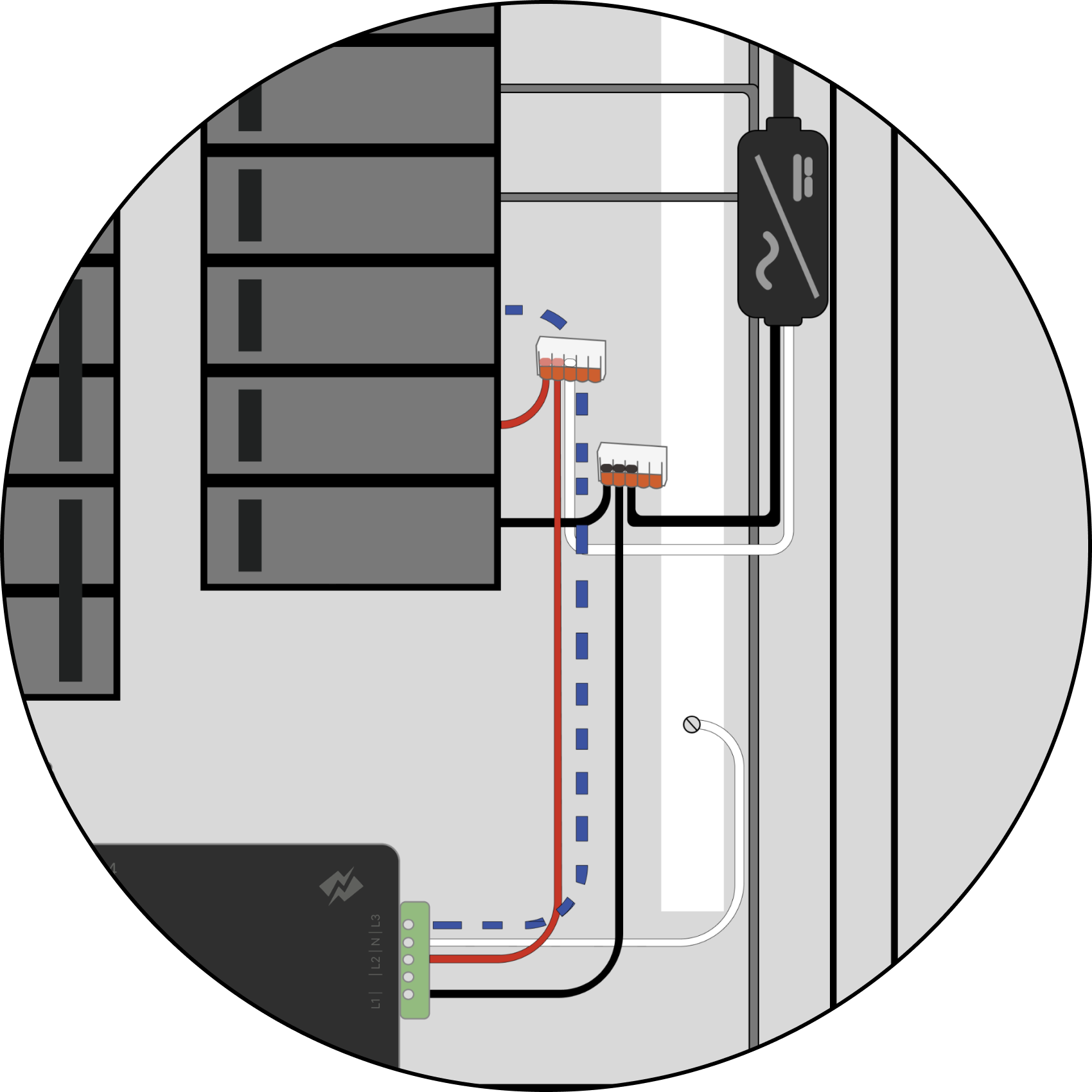
- Land white (N) on the neutral bus bar.
- Turn off the two stacked breakers (or the 2-pole).
- Join black (L1), the power supply's black input lead and a splicing wire in a 5-port Wago. Land the splicing wire on the first pole.
- Join red (L2), the power supply's white input lead and a splicing wire in the second 5-port Wago. Land the splicing wire on the second pole.
- Blue (L3):
- Battery on CT 3: put blue (L3) in a spare port of the L1 Wago.
- 3-phase: land blue on the third phase (Blue L3).
- Otherwise: cap blue.
The power supply's input leads: black to L1, white to L2. See the harness drawing.
5b. Splice into in-use breakers
Most panels don't have empty breakers. Splice into two stacked in-use breakers.
Split-core CT kit
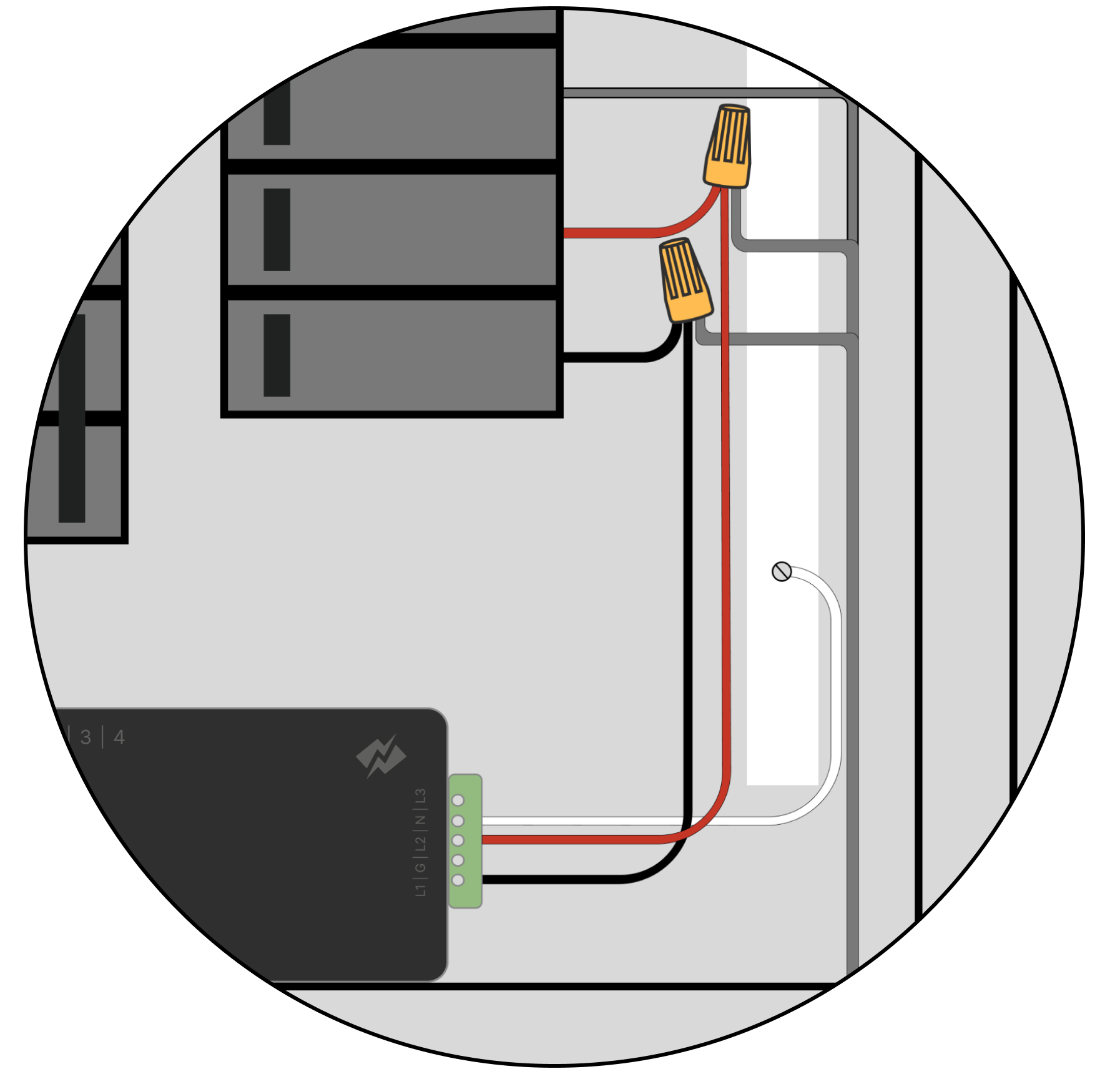
- Land white (N) on the neutral bus bar.
- Turn off the two stacked breakers and remove their circuit wires.
- First breaker: join the circuit wire, black (L1) and a splicing wire with a wire nut. Land the splicing wire on the breaker.
- Second breaker: join the circuit wire, red (L2) and a splicing wire with a wire nut. Land the splicing wire on the breaker.
- Blue (L3):
- Battery on CT 3: add blue (L3) to the first breaker's wire nut, with black (L1). That nut then holds four conductors: use one listed for four.
- 3-phase: land blue on the third phase (Blue L3).
- Otherwise: cap blue.
Flex (Rogowski) kit
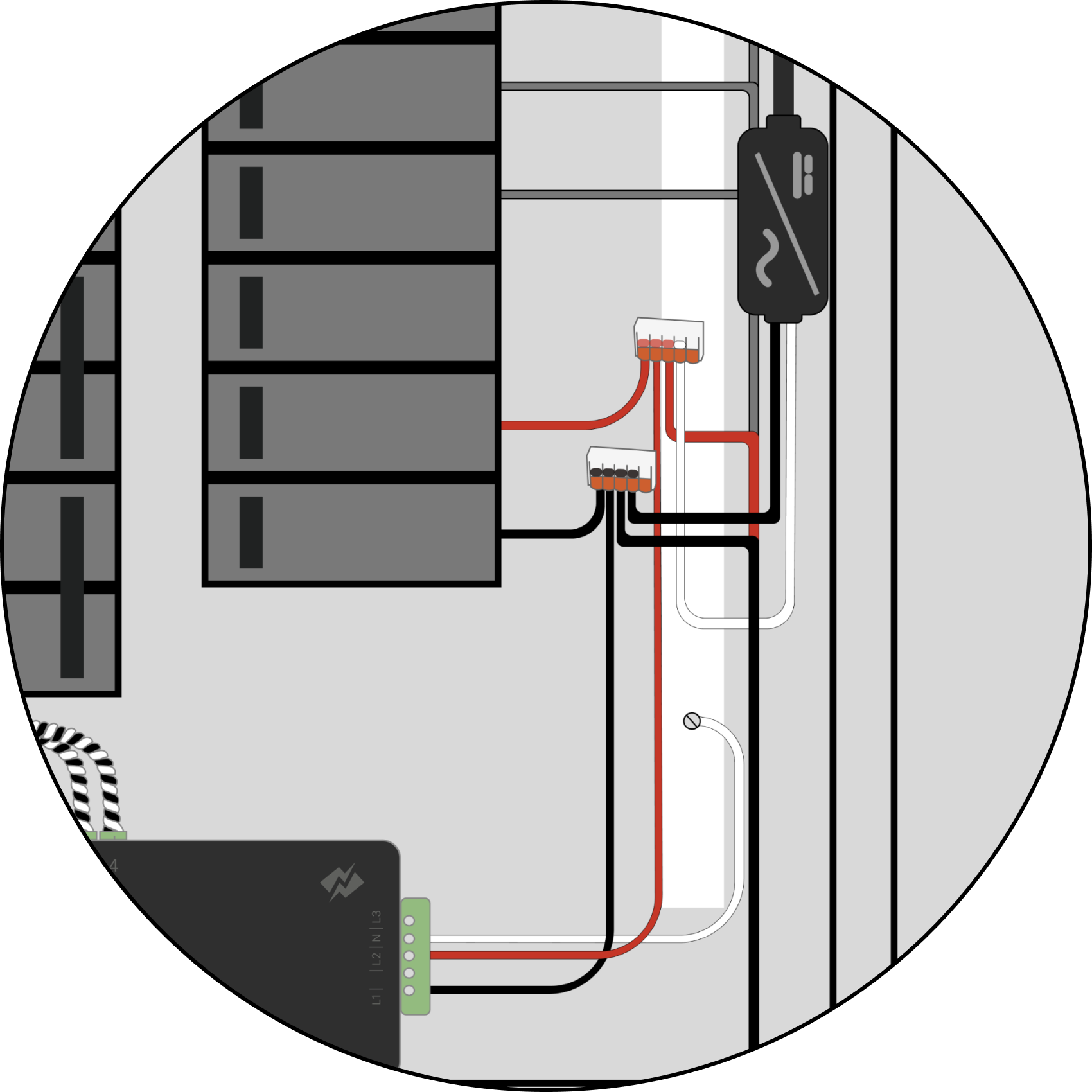
- Land white (N) on the neutral bus bar.
- Turn off the two stacked breakers and remove their circuit wires.
- First breaker, 5-port Wago: the splicing wire, black (L1), the power supply's black input lead and the circuit wire. One port stays spare. Land the splicing wire on the breaker.
- Second breaker, 5-port Wago: the splicing wire, red (L2), the power supply's white input lead and the circuit wire. One port stays spare. Land the splicing wire on the breaker.
- Blue (L3):
- Battery on CT 3: put blue (L3) in the spare port of the first breaker's (L1) Wago. All five ports are then full.
- 3-phase: land blue on the third phase (Blue L3).
- Otherwise: cap blue.
To use a Wago: lift the levers, insert each stripped wire fully, snap the levers closed, then tug each wire to confirm it holds.
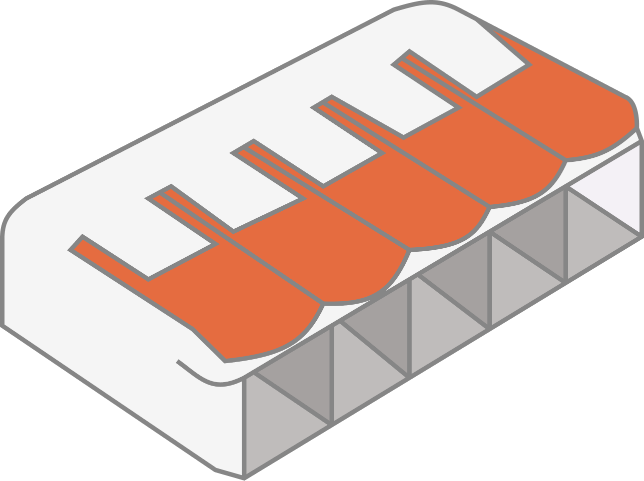
Note
A breaker larger than 15 A is fine if the splicing wire gauge matches the existing circuit wire and meets national and regional codes.
5c. AFCI or GFCI breaker
On an AFCI/GFCI breaker, neutral lands on the breaker's neutral terminal, not the neutral bus.
Split-core CT kit
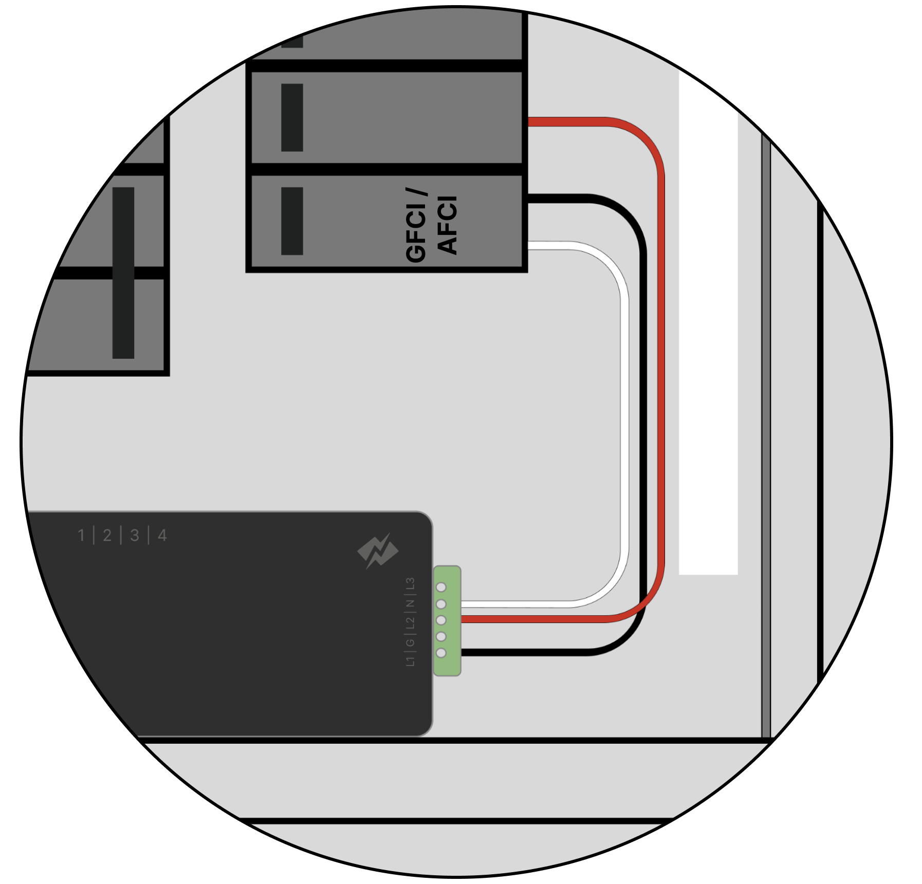
- Land black (L1) on the breaker's hot terminal.
- Land white (N) on the breaker's neutral terminal. Not the neutral bus.
- Land red (L2) on the adjacent single-pole breaker.
- Blue (L3):
- Battery on CT 3: join black (L1), blue (L3) and a splicing wire with a wire nut. Land the splicing wire on the breaker's hot terminal in place of black.
- 3-phase: land blue on the third phase (Blue L3).
- Otherwise: cap blue.
Flex (Rogowski) kit
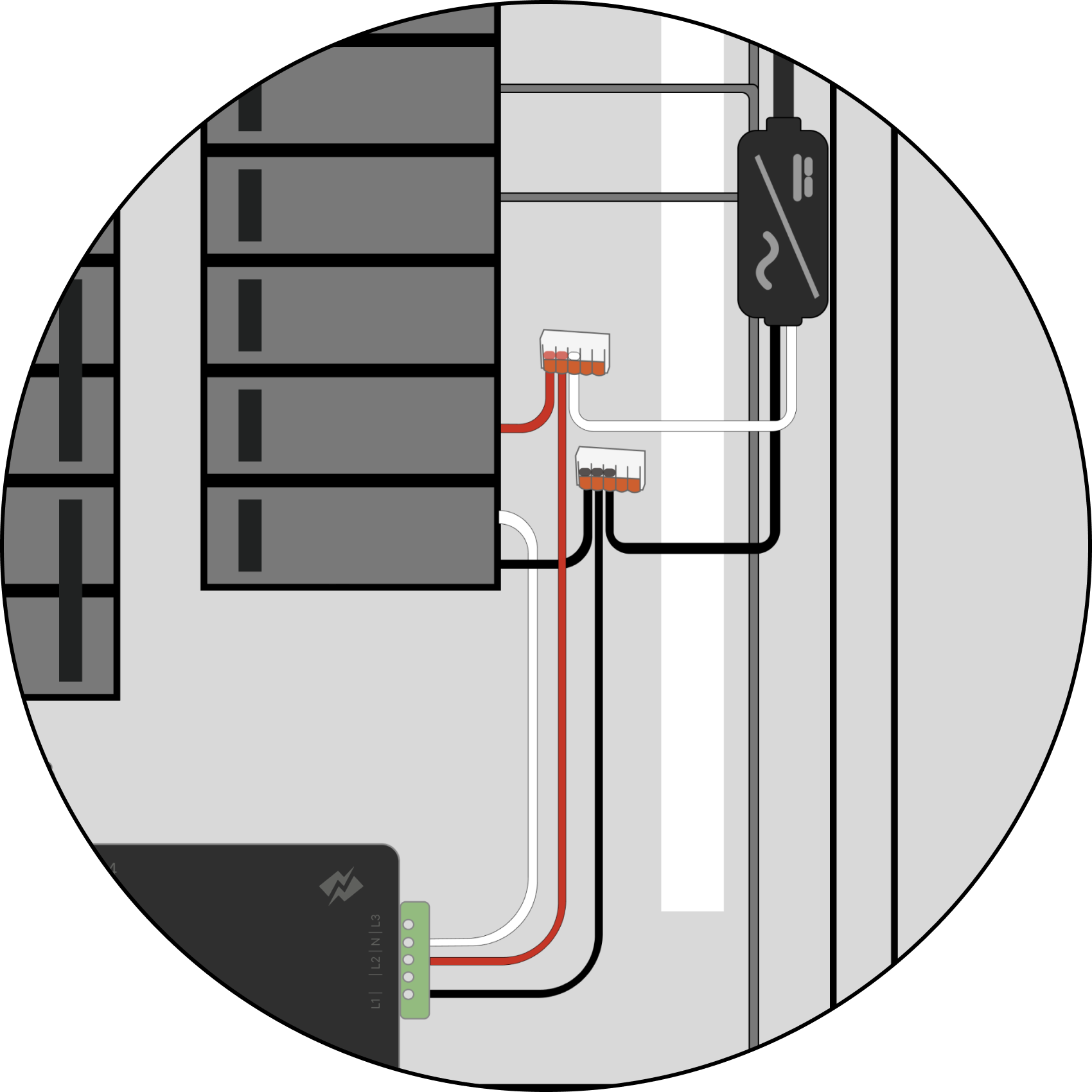
- Join black (L1), the power supply's black input lead and a splicing wire in a 5-port Wago. Land the splicing wire on the breaker's hot terminal.
- Land white (N) on the breaker's neutral terminal. Not the neutral bus.
- Join red (L2), the power supply's white input lead and a splicing wire in the second 5-port Wago. Land the splicing wire on the adjacent single-pole breaker.
- Blue (L3):
- Battery on CT 3: put blue (L3) in a spare port of the L1 Wago (the one on the breaker's hot terminal).
- 3-phase: land blue on the third phase (Blue L3).
- Otherwise: cap blue.
Blue L3: battery on CT 3, or 3-phase
- Battery on CT 3 (the main use): splice blue (L3) to black (L1) in the same L1 connection, on the same breaker. It is CT 3's voltage reference for reading whether the battery is charging or discharging. Split-core: add it to the L1 wire nut. Flex: use a spare port on the L1 Wago. Use a connector listed for the number of conductors.
- 3-phase 208Y/120 V (the only other use): land blue (L3) on a third adjacent breaker pole, on the third phase.
- Anything else: cap blue (L3). Solar alone never needs L3.
Danger
Never land blue (L3) on neutral. L3 is voltage sensing only: hot (line) conductors only.
Step 6: Connect the internet
The monitor connects over Wi-Fi, Ethernet or both. If both are connected, it uses Ethernet. Wi-Fi is 2.4 GHz only.
6a. Wi-Fi (most common)

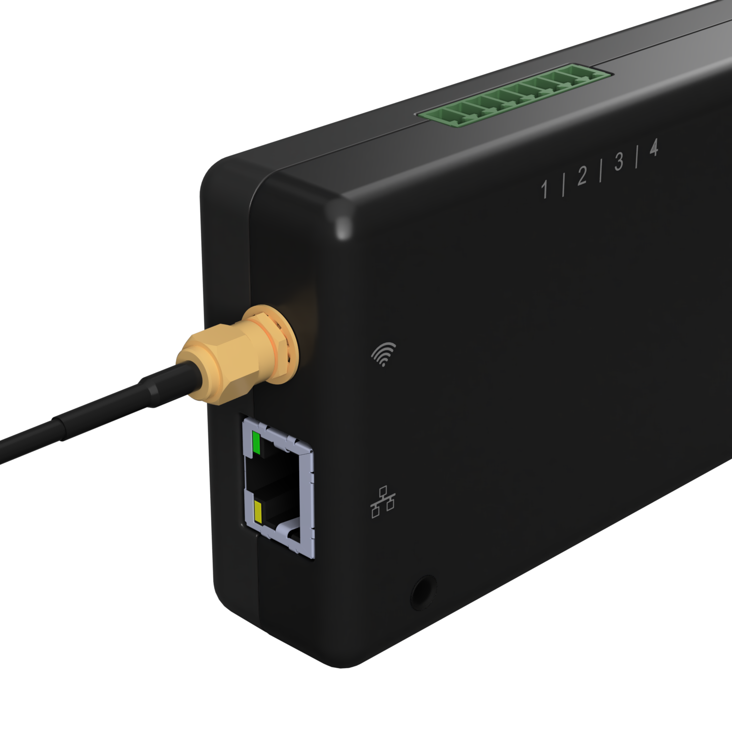
- Remove a knockout from the panel.
- Feed the antenna through so the antenna itself is outside the metal enclosure. Inside a wall is fine.
- Screw the antenna cable onto the coax connector on the left side of the monitor (marked with the Wi-Fi symbol). Make it finger-tight.
- Seat the knockout plug on the antenna cable in the hole.
Warning
An antenna left inside the metal panel may not reach the Wi-Fi.
6b. Ethernet

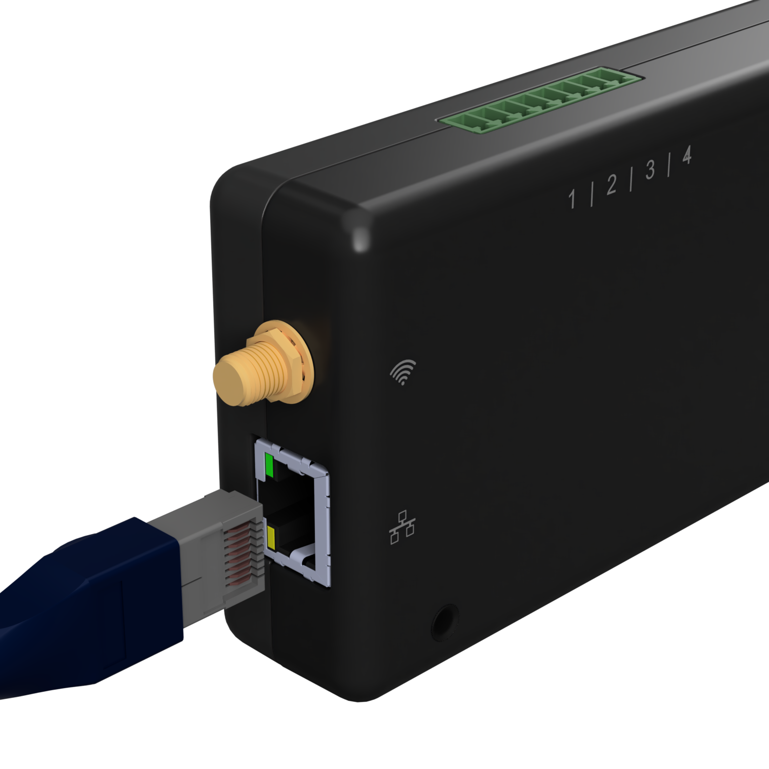
- Run a Cat5e or better cable from the router, switch or modem to the panel.
- Remove a knockout, feed the cable through and plug it into the RJ45 port on the left side of the monitor (marked with the Ethernet symbol).
Step 7: Install the main sensors (CT 1 and CT 2)
The rule: CT 1 and CT 2 clamp both hots of the breaker the EMS protects, just above or just below it. Nothing may be tapped in between. One sensor per hot conductor, never on the neutral.
- Monitor in the main panel: the main breaker. Usually the service conductors between the meter and the main breaker.
- Monitor in a subpanel: that subpanel's feeder conductors, at the feeder breaker or the subpanel lugs.
- The arrow always points toward the load (into the panel the breaker feeds). If CT 3 is on a battery, the battery is the load: the app shows a negative value while the battery exports.
- Port 1 on L1 is recommended, not required.
- Never clamp the mains on solar or battery conductors, a parallel feeder, or anything downstream of another breaker.
Split-core CT kit


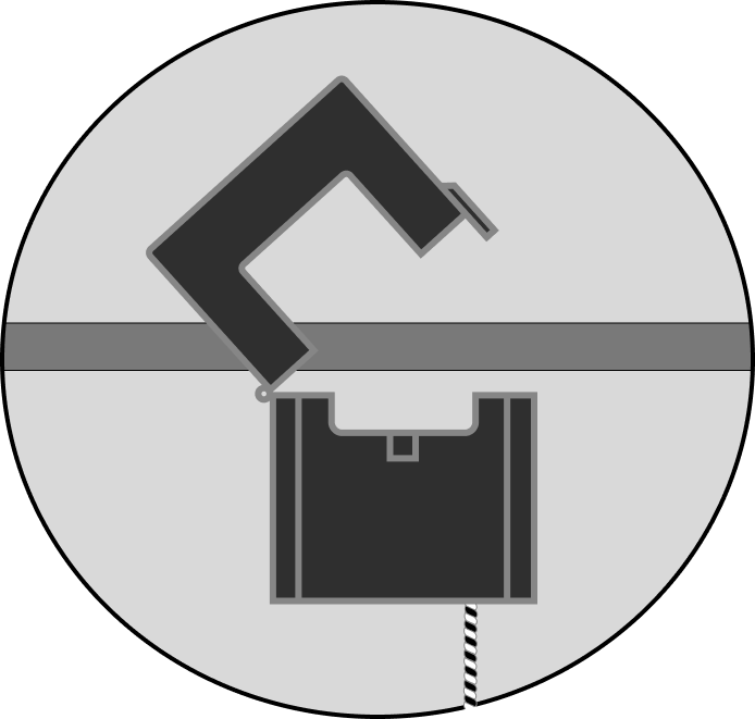
- Open the clasp on a 200 A CT, place it around one hot conductor and snap it fully shut.
- Turn it so the arrow points toward the load.
- Repeat on the second hot conductor.
- Plug the two CT plugs into ports 1 and 2.
Flex (Rogowski) kit

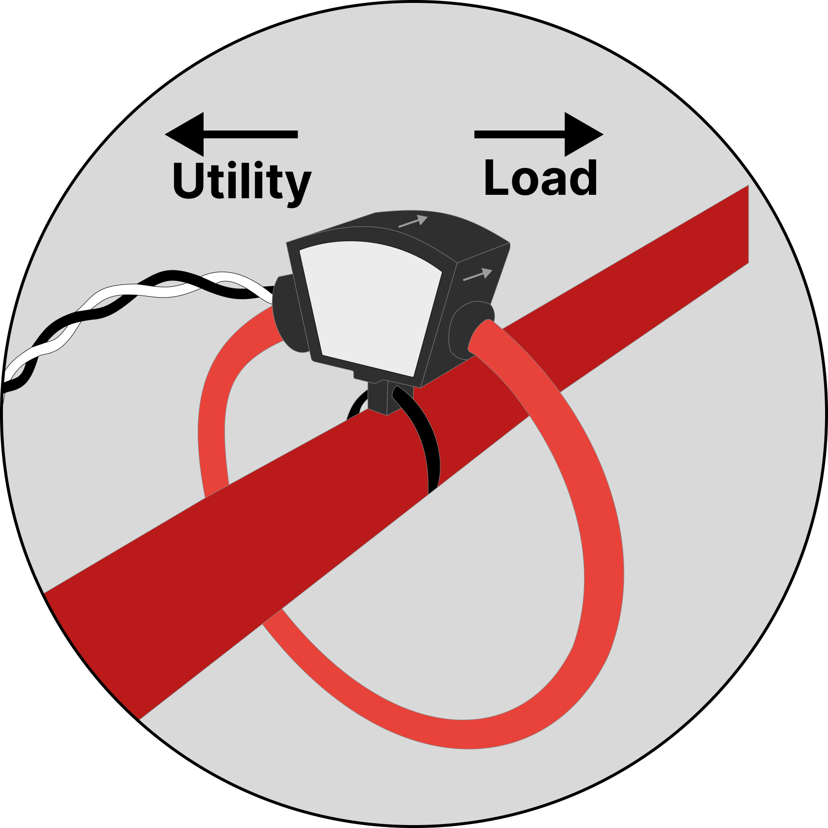
- Plug a 12 V harness from the sensor power supply into each integrator.
- Open a coil, wrap it around one hot conductor and lock the end back into the clasp.
- Turn it so the arrow points toward the load.
- Zip-tie the coil head to the conductor.
- Repeat on the second hot conductor.
- Plug each integrator's signal cable into port 1 or 2.
Full details in Flexible (Rogowski) sensors.
Solar or battery on site?
- Breaker-fed (backfed) solar or battery in the panel: the mains stay at the protected breaker, as above. They then read the home's net load.
- Line-side (supply-side) tap, case A10: the mains go below the tap, between the tap and the main breaker. CT 3 never goes on the tap.
- Battery tied in between two breakers, cases A7a and A7b: see the diagram before you clamp anything.
See Wiring diagrams for every case.
Danger
⚡ DANGER: The service mains are energized!
Step 8: Install CT 3 and CT 4

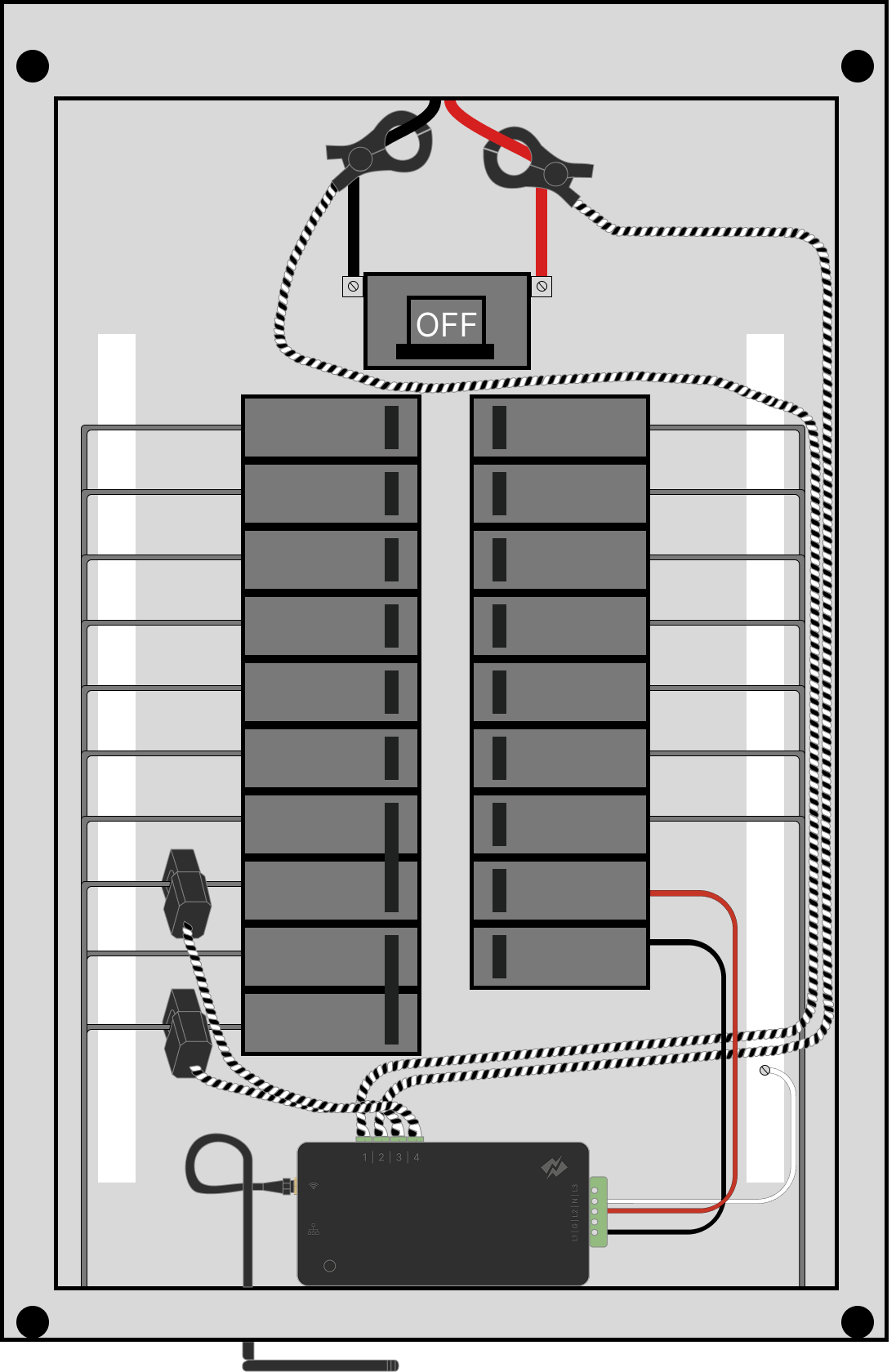
CT 4 always goes on the EV charger (Autel). CT 3 goes on one of these:
| CT 3 on | When | App answer to "How are CT 3 and CT 4 installed?" |
|---|---|---|
| The Autel's second leg | No battery or solar to monitor, and no other load requested. The most accurate charger reading | One 240V circuit, then pick the Autel under "Is this your EV charger?" |
| A battery's L1 (black) conductor | A battery is installed. Arrow toward the battery: the battery is the load, and the app shows a negative value while it exports. Splice blue L3 to L1 (Step 5) | Two different circuits. CT 4 is the Autel |
| A solar inverter output | Solar only, no battery. Arrow toward the inverter: treat it as the load. It reads negative while producing. No L3 | Two different circuits. CT 4 is the Autel |
| One other load | The homeowner wants a load such as a water heater, AC or a second EV charger monitored | Two different circuits. CT 4 is the Autel |
- Open the clasp on a 50 A branch CT and place it around a hot conductor (never the neutral) of the circuit. Snap it shut.
- Turn it so the arrow points toward the load. On a battery or solar line, the battery or inverter is the load.
- Plug CT 4 into port 4 and CT 3 into port 3.
- Write down what CT 3 is on. You enter it in the app.
Warning
- CT 3 and CT 4 must both be downstream of CT 1–2: the mains must carry everything CT 3 and CT 4 see.
- A CT 3 on a battery or solar line is for monitoring only. The EMS controls the Autel from CT 1–2.
- One CT on a 240 V load reads correctly only when that load is balanced, such as an EV charger. Set that circuit to 240 V in the app. One CT on an unbalanced multi-pole load won't read accurately.

Step 9: Dress the leads
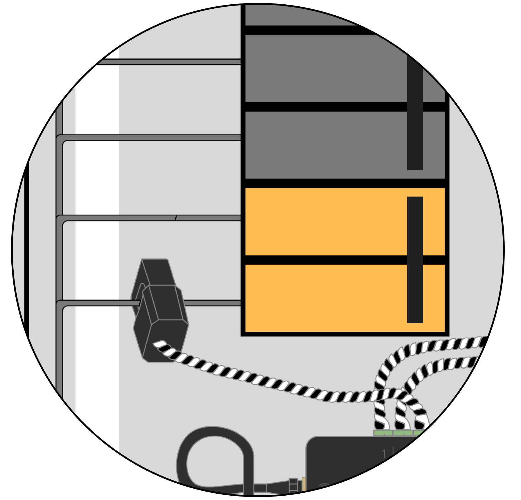
- Don't cut, shorten, splice or extend any sensor lead. Coil the excess and tie it off.
- Keep each CT's leads twisted and in their factory screw-terminal positions.
- Route leads so they don't touch live terminals or buses, don't block ventilation openings and stay clear of breaker arc venting.
- Keep every sensor lead inside the panel where the monitor is mounted. Never run leads between panels.
Warning
Shortened and re-terminated leads have reversed the polarity on a live install: every channel read negative. Charging still worked, but the energy data was wrong and the EMS read import as export.
Step 10: Photograph the sensors
Before the cover goes on, take CT placement photos on the homeowner's phone:
- Wide enough to trace each main sensor to its conductor and each lead to its port.
- With every arrow or "Load" label readable.
- Leads that snake out of frame, or a plug that looks like it straddles two ports, fail review.
These are required closeout photos. See Before you leave.
Step 11: Cover on, power on
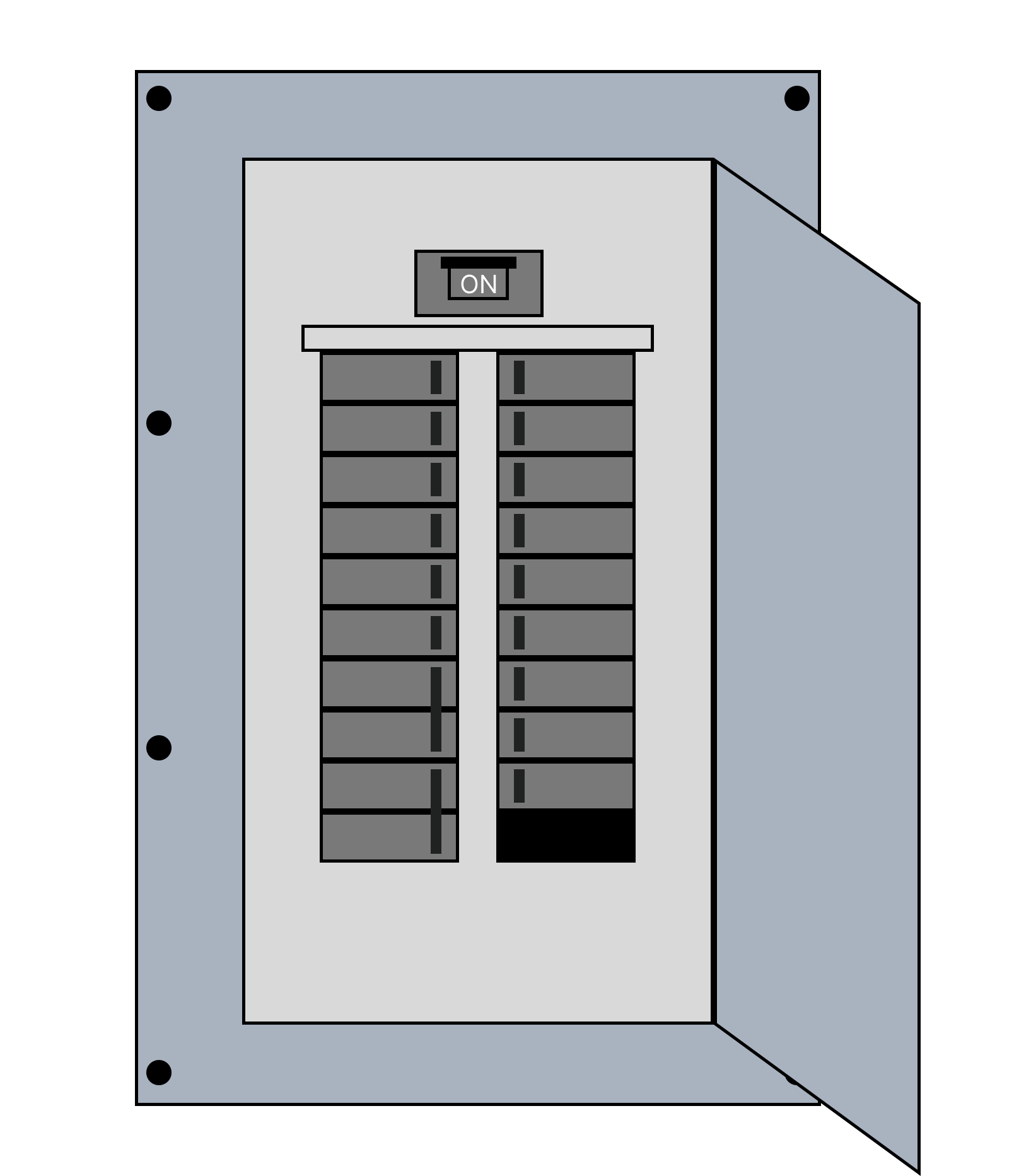
- Finish all cabling first. Once the cover is on, the antenna connector, Ethernet port and sensor ports can't be reached.
- Replace the cover and its screws.
- Turn back on every breaker you turned off, then the main.
- Check the status light within a few seconds: - Purple with a blue blink: powered and ready for setup. Continue. - Orange: the harness doesn't match the service type. Fix it now, before you leave the panel. Recheck Step 5. - No light: no power. Recheck the harness and the supply breaker.
Step 12: Set up the EMS
Continue with EMS setup, Step 4. Check the Autel app first: the firmware update should be finished and the factory reset done.
Two Energy Monitors (main panel + subpanel)
Some homes need two Energy Monitors. This applies only when both are true:
- The Autel circuit is in a subpanel, and
- Both the main service and the subpanel feeder need load management to stay within their ratings (the load calculation fails at both levels without it).
Note
If the subpanel feeder has enough calculated capacity for the charger under a standard load calculation, one Energy Monitor in the main panel is enough, even when the charger is in the subpanel. Use the standard steps and skip this section.
Install each monitor with Steps 1–11, one panel at a time. All sensors for a monitor stay inside the panel where that monitor is mounted.
Subpanel monitor
- CT 1–2 on the subpanel's feeder conductors, arrows toward the subpanel's breakers, so it measures the whole subpanel.
- CT 4 on the Autel.
- Voltage harness on breakers in the subpanel.
- App: Subpanel, rating = the feeder breaker.
Main panel monitor
- CT 1–2 on the service conductors per Step 7, including the solar and battery cases.
- CT 3 and CT 4 on other circuits in the main panel. Never on the subpanel's feeder breaker: the subpanel monitor covers the feeder.
- App: Main panel, rating = the main breaker.
Configuration
- Read each rating from the breaker label itself. The EMS enforces exactly what you enter.
- Both monitors need an internet connection. Check Wi-Fi at both panels, or run Ethernet to each.
- The charging limit is set by whichever panel has less headroom at that moment. If either monitor loses power or its connection, charging pauses after a short safety timeout.
- See cases B1 and B2. Call NeoCharge before scheduling a two-monitor job.
Danger
⚠ WARNING: This system supports one EV charger per branch circuit. Never connect two EV chargers to a single branch circuit. The EMS doesn't manage loads sharing one branch circuit, and doing so may overload the circuit.
Something wrong or unclear on this page? Email support@getneocharge.com. Rev 005 is the controlled copy.
