




Guide de l'installateur Energy Monitor + EMS
Capteurs flexibles (Rogowski)
The flexible-sensor kit in depth: when to use it, kit parts, mounting the power supply and integrators, coil orientation and centering, cabling and flex-specific troubleshooting.
The flexible kit replaces the two 200 A split-core main CTs with two flexible Rogowski coils. Everything else (the monitor, harness, antenna and the two 50 A branch CTs on ports 3 and 4) is the same as the split-core kit. This section covers what's different. The shared steps are in Install the Energy Monitor.
When to use the flexible kit
- Use it wherever split-core CTs won't close fully around the service or feeder conductors.
- Meter-mains usually need it. So do tight gutters, large or alternating conductors, and service disconnects that leave no straight run.
- Decide at scoping, from the panel photos. Don't start a flex job until the flexible sensors are on site.
Kit parts
| Part | Qty | What it does |
|---|---|---|
| Flexible Rogowski coil with integrator | 2 | One coil per hot conductor. The integrator turns the coil signal into a reading for the monitor |
| Signal wire with 4-pin plug | 2 | Plugs into each integrator. Carries the twisted signal pair to port 1 or 2 (2-pin plug) and the 12 V red and black leads |
| 12 V sensor power supply (Mean Well IRM-30-12ST) | 1 | Powers both integrators. Black and red 12 V output splits to both signal wires. Input: black to L1, white to L2 |
| Wago lever connectors, wire nuts, splicing wire | — | Two 5-port Wagos: one for L1, one for L2 |
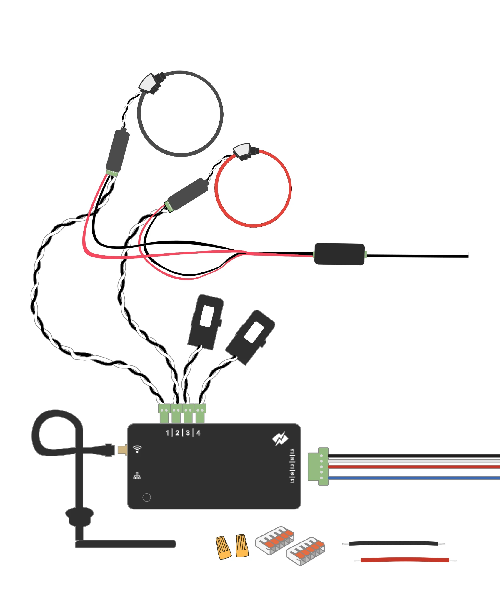
How the harness connects
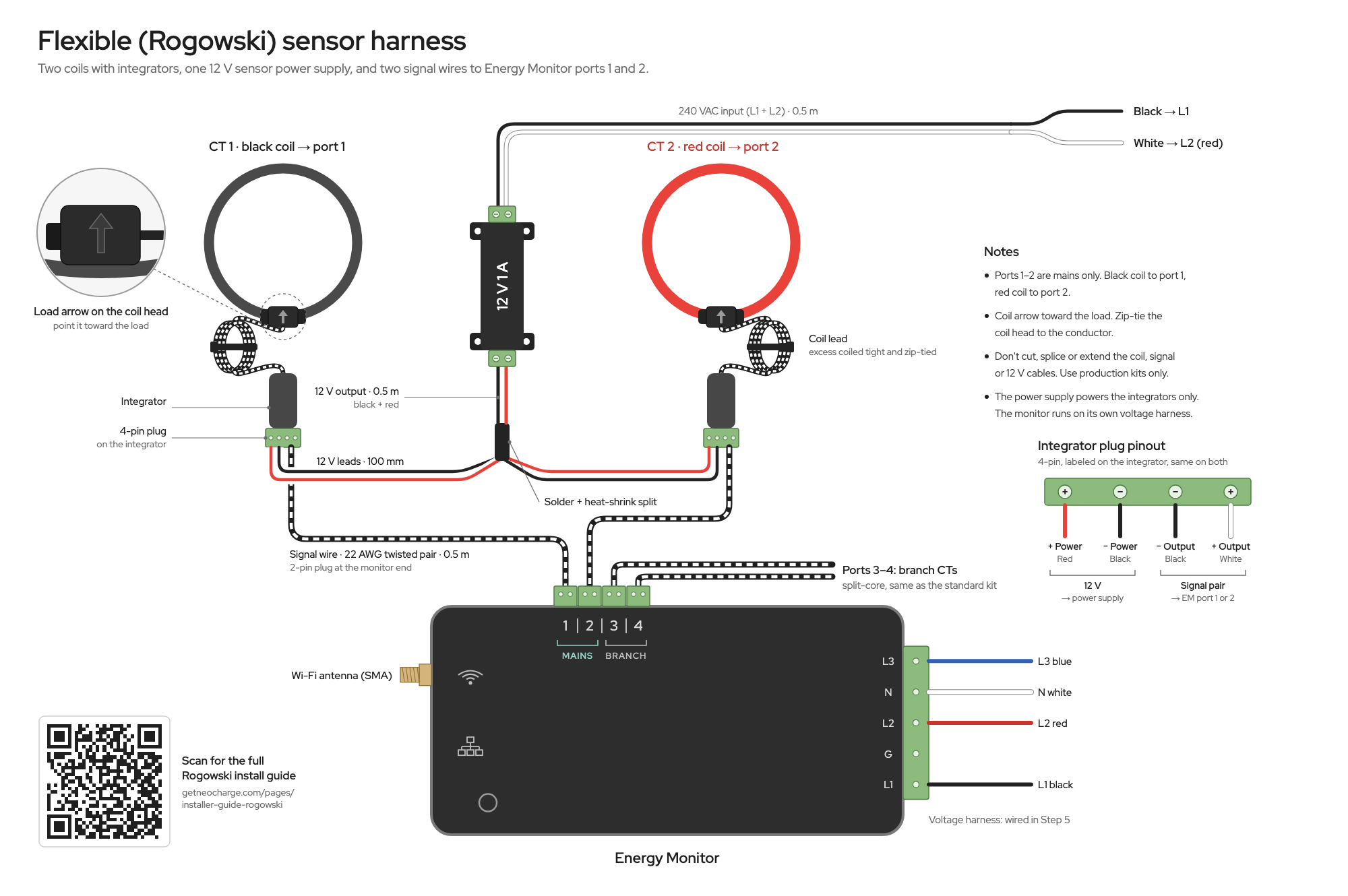
- Each 4-pin plug goes into one integrator. It carries that coil's twisted signal pair and one red and one black 12 V lead.
- 12 V output: one black and one red wire leave the power supply and split at a soldered, heat-shrunk joint, so each plug gets one black and one red.
- AC input (the other end of the power supply): black to L1, white to L2.
- Signal pairs: CT 1 to port 1, CT 2 to port 2. On the monitor, ports run 1 to 4.
Warning
Use production kits only: the harness, power supply and integrators exactly as shipped. Don't mix in sample parts, and don't use any third-party coils, integrators or power supplies.
Mount the power supply and integrators
- Plan the layout before you mount anything: the monitor, the power supply and the two integrators all go inside the panel.
- Keep all of them at least 50.8 mm (2 in) from live parts: primary conductors, terminals and lugs. Insulated cables are fine.
- Put the integrators where each coil's cable reaches its integrator, and each signal cable reaches ports 1 and 2, without strain and without cutting or extending anything.
- Don't mount anything to an energized part, over ventilation openings or in the path of breaker arc venting.
Wire the power supply
The power supply's AC input has two leads: black to L1 and white to L2. Both land with the monitor's harness on the same two breakers. Full wiring with photos is in Step 5.
- Black (L1): join the black input lead with the monitor's black (L1) in the L1 Wago.
- White (L2): join the white input lead with the monitor's red (L2) in the L2 Wago. It never goes on the neutral bus.
- AFCI/GFCI breaker: black goes in the L1 Wago to the breaker's hot terminal; white goes in the L2 Wago with the monitor's red (L2) to the adjacent single-pole breaker.
The monitor and the power supply together draw less than 1.5 A.
Note
Battery on CT 3? Blue L3 goes in the L1 Wago.
If CT 3 monitors a battery, the monitor's blue (L3) must connect to black (L1): put it in a spare port of the L1 Wago. L3 is CT 3's voltage reference: without it, the monitor can't tell the battery charging from discharging. The only other use for L3 is the third phase of a 3-phase 208Y/120 V service. Otherwise cap it. See Blue L3.
What goes in each Wago
| Step 5 case | L1 Wago (5-port) | L2 Wago (5-port) |
|---|---|---|
| 5a. Empty breakers | Splicing wire to the L1 pole, black (L1), power supply black, blue (L3) if a battery is on CT 3 | Splicing wire to the L2 pole, red (L2), power supply white |
| 5b. Splice into in-use breakers | Splicing wire, circuit wire, black (L1), power supply black, blue (L3) if a battery is on CT 3 (fills the last port) | Splicing wire, circuit wire, red (L2), power supply white |
| 5c. AFCI or GFCI breaker | Splicing wire to the breaker's hot terminal, black (L1), power supply black, blue (L3) if a battery is on CT 3 | Splicing wire to the adjacent single-pole breaker, red (L2), power supply white |
White (N) never goes in a Wago: it lands on the neutral bus, or on the breaker's neutral terminal for 5c.
Connect power and signal
- Plug a signal wire's 4-pin plug into each integrator. Push it fully home and tighten the screws to 0.34 N·m (3.0 lb-in). The plug carries both the signal pair and the 12 V leads.
- Route each twisted signal pair to the monitor and plug its 2-pin plug into port 1 (CT 1) or port 2 (CT 2). Mind the polarity. Ports 1 and 2 are for the mains on every install.
- Port 1 on the L1 conductor is recommended, not required.
- Keep the signal cable leads twisted.
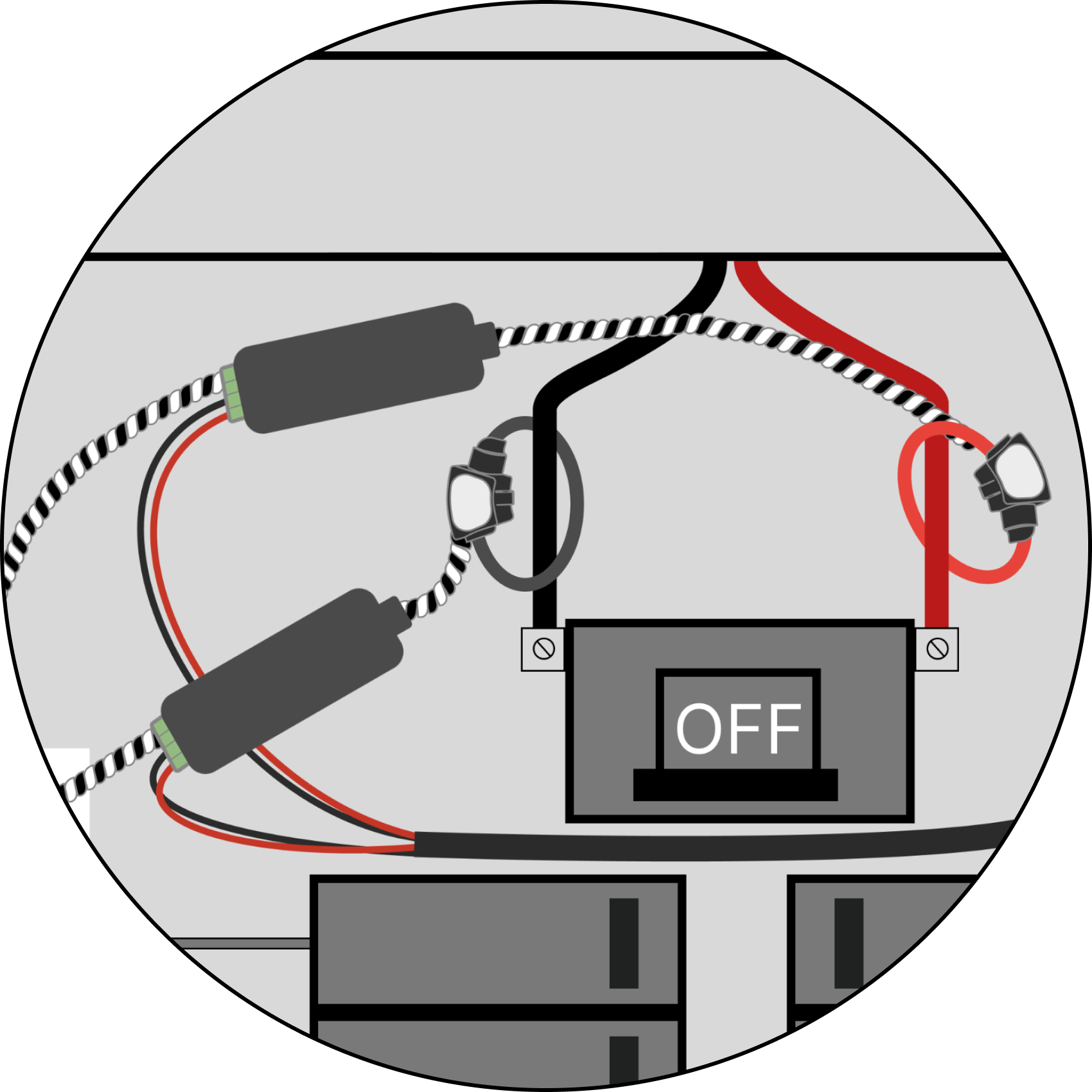
Install the coils
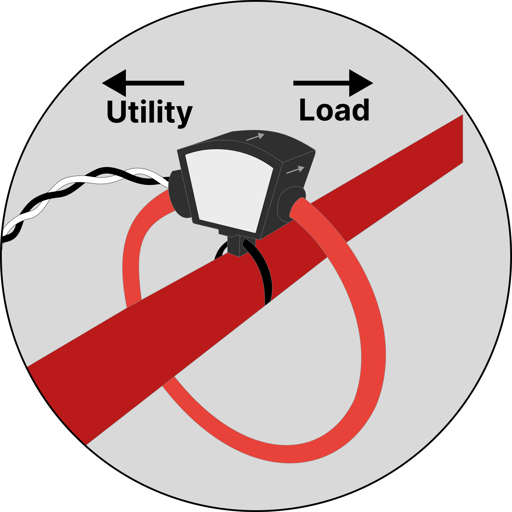
- Release the latch to open one end of the coil.
- Wrap the coil around one hot service or feeder conductor. Never the neutral.
- Lock the end back into the clasp. It must click closed: an open or half-latched coil reads low or erratic.
- Turn the coil so the arrow points toward the load: into the panel the breaker feeds.
- Zip-tie the coil head to the conductor. That keeps the coil from sliding or turning, so the arrow stays pointed toward the load.
- Repeat on the second hot conductor.
The placement rule is the same as for split-core CTs: both hots of the breaker the EMS protects, just above or just below it, nothing tapped in between. See Step 7 and Wiring diagrams.
Danger
⚡ DANGER: The service mains are energized! Wrapping a coil means working right at the live service conductors. Wear insulated gloves and eye protection.
Cabling rules
- Don't cut, splice or extend the coil cable, the integrator signal cable or the 12 V power cables. They are calibrated sensor components.
- Coil the excess and tie it off. Keep it away from live terminals and buses.
- Keep every cable inside the panel where the monitor is mounted.
Flex troubleshooting
| Symptom | Likely cause | Fix |
|---|---|---|
| Both mains read zero | The power supply has no power | Check its breaker is on and both input leads are secure in the L1 and L2 Wagos |
| One main reads zero | That integrator's 12 V harness or signal cable isn't seated | Reseat the 12 V plug in the integrator and the signal plug in port 1 or 2 |
| A main reads negative while the home is drawing power | The coil faces the wrong way | Turn the coil so the arrow points toward the load. (With solar or a battery, rule out export first. See Readings are negative.) |
| A main reads low or jumps around | Coil not fully latched, or the coil has slid or turned | Relatch the coil and zip-tie the coil head to the conductor |
| Mains read but the charger channel doesn't | CT 4 problem, not the flex kit | See Readings don't match |
More symptoms are in Troubleshooting.
Something wrong or unclear on this page? Email support@getneocharge.com. Rev 005 is the controlled copy.
